Dc-dc converters

a dc-dc converter and converter technology, applied in the field of voltage converters, can solve the problems of increasing the switching speed, requiring a much tighter switch, and reducing the supply voltage of the processor, so as to improve the control of the dc-dc converter

Active Publication Date: 2011-01-27
CIRRUS LOGIC INC
View PDF18 Cites 137 Cited by
  • Summary
  • Abstract
  • Description
  • Claims
  • Application Information

AI Technical Summary

Benefits of technology

[0010]It is therefore an aim of the present inventi

Problems solved by technology

These trends result in two design challenges for DC-DC converters to service these applications: one induced by the choice of the value of the low voltage; the other by battery technology lagging behind the change to lower processor supply voltages.(i) The reduction in processor supply voltage requires a much tighter control—in absolute terms—of the DC-DC converter output voltage under all prevailing processor load and battery conditions.
If the control over the processor supply voltage is not sufficient, problems with under or overvoltage may occur: both equally undesirable.(ii) Since the battery terminal voltage has not dropped appreciably, and the duty cycle of a DC-DC converter is giv

Method used


Image

  • Dc-dc converters
  • Dc-dc converters
  • Dc-dc converters

Examples


Embodiment Construction

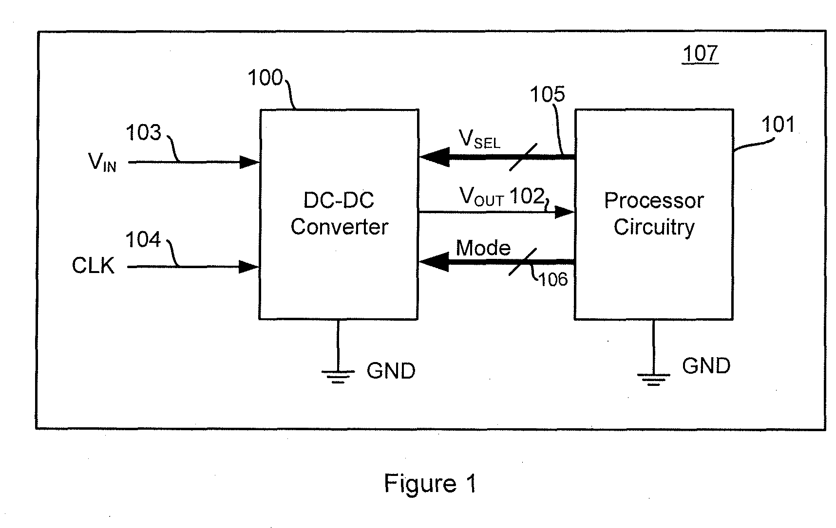
[0087]FIG. 1 shows a typical application where processor circuitry 101, which may, for example, be a processor of a portable electronic device 107, is supplied with a voltage VOUT 102 by a DC-DC converter 100. The DC-DC converter 100 receives an input voltage VIN 103 and an external clock signal CLK 104 and outputs the required voltage output VOUT 102. It is usual for the supply voltage of a processor to be reduced when the processor is idling in order to save power, and then to ramp up to a more normal operating voltage where the processor may achieve full operating speed. The processor circuitry 101 therefore provides voltage select signals VSEL 105 to the DC-DC converter 100 to select an appropriate voltage output VOUT. The voltage select signals may be digital signals for controlling a programmable element of the DC-DC converter, such as a level shifter, as will be described later. The DC-DC converter 100 may also be operable in various modes, as will be described later, and the...


PUM


Abstract

Methods and apparatus for control of DC-DC converters. The DC-DC converter is operable so that the low side supply switch may be inhibited from turning on in a cycle following the high side supply switch turning off. Turn on of the low side switch is inhibited if the time between turn off of the high side switch and the inductor (L) current reaching zero is less than a predetermined duration. Inhibiting the low side switch from turning on can prevent the inductor current from going negative, which would reduce the efficiency of the converter. When turn on of the low side switch is inhibited the inductor current flows through a parallel path, such as a parasitic body diode associated with the low side switch, which allows current flow in one direction only.

Description

[0001]This application claims the benefit of U.S. Provisional Application No. 61 / 228,002, filed Jul. 23, 2009, and U.S. Provisional Application No. 61 / 261,123, filed Nov. 13, 2009.BACKGROUND OF THE INVENTION[0002]1. Field of the Invention[0003]This invention relates to voltage converters, especially to DC-DC or switched voltage regulators and to methods and apparatus for control of such regulators.[0004]2. Description of the Related Art[0005]In electronic equipment in general, and particularly for fast moving segments such as portable consumer devices such as mobile phones, MP3 players etc, there is a relentless push to use the latest processor technology to increase the device capability and feature set while reducing power and cost. As the next generation of processors start to become available, they need to operate from lower voltages than previous generation processors so as to allow use of the reduction in process feature size, i.e. W / L, that enables a greater level of integrat...

Claims


Application Information

Patent Timeline
IPC IPC(8): G05F1/00H02M1/00H02M1/38
CPCH02M1/38H02M3/1588G05F1/46Y02B70/1466H02M2001/0009H02M1/0009Y02B70/10G05F1/575H02M1/08H02M1/32H02M1/36H02M3/156H02M3/158H02M3/1582H02M3/33507H03K17/04206H03K19/01742H02H7/1213H02M1/0032
Inventor NOTMAN, ANDREWMCCLOY-STEVENS, MARK
Owner CIRRUS LOGIC INC
Why Eureka
Try Eureka