Pressure sensor failure diagnosis method and common rail type fuel injection control apparatus

a technology of pressure sensor and failure diagnosis, which is applied in the direction of electrical control, process and machine control, etc., can solve the problems of unnecessary increase of rail pressure, redundancy in control operation, and unnecessary command to increase rail pressure, etc., and achieves the effect of simple structur

Inactive Publication Date: 2011-01-27
BOSCH CORP
View PDF7 Cites 34 Cited by
  • Summary
  • Abstract
  • Description
  • Claims
  • Application Information

AI Technical Summary

Benefits of technology

[0008]The present invention has been made in view of the above-described circumstances, and provides a pressure sensor failure diagnosis method and a common rail type f...

Problems solved by technology

However, in the above-described failure diagnosis method, in order to detect the failure of the pressure sensor, it is necessary to issue the command to increase the rail pressure unnecessarily, irrespective of an actual fue...

Method used


Image

  • Pressure sensor failure diagnosis method and common rail type fuel injection control apparatus
  • Pressure sensor failure diagnosis method and common rail type fuel injection control apparatus
  • Pressure sensor failure diagnosis method and common rail type fuel injection control apparatus

Examples


Embodiment Construction

[0026]An embodiment of the invention will be described below with reference to FIG. 1 to FIG. 6.

[0027]It will be noted that the members and arrangements described below are not intended to limit the present invention and can be variously modified within the scope of the gist of the present invention.

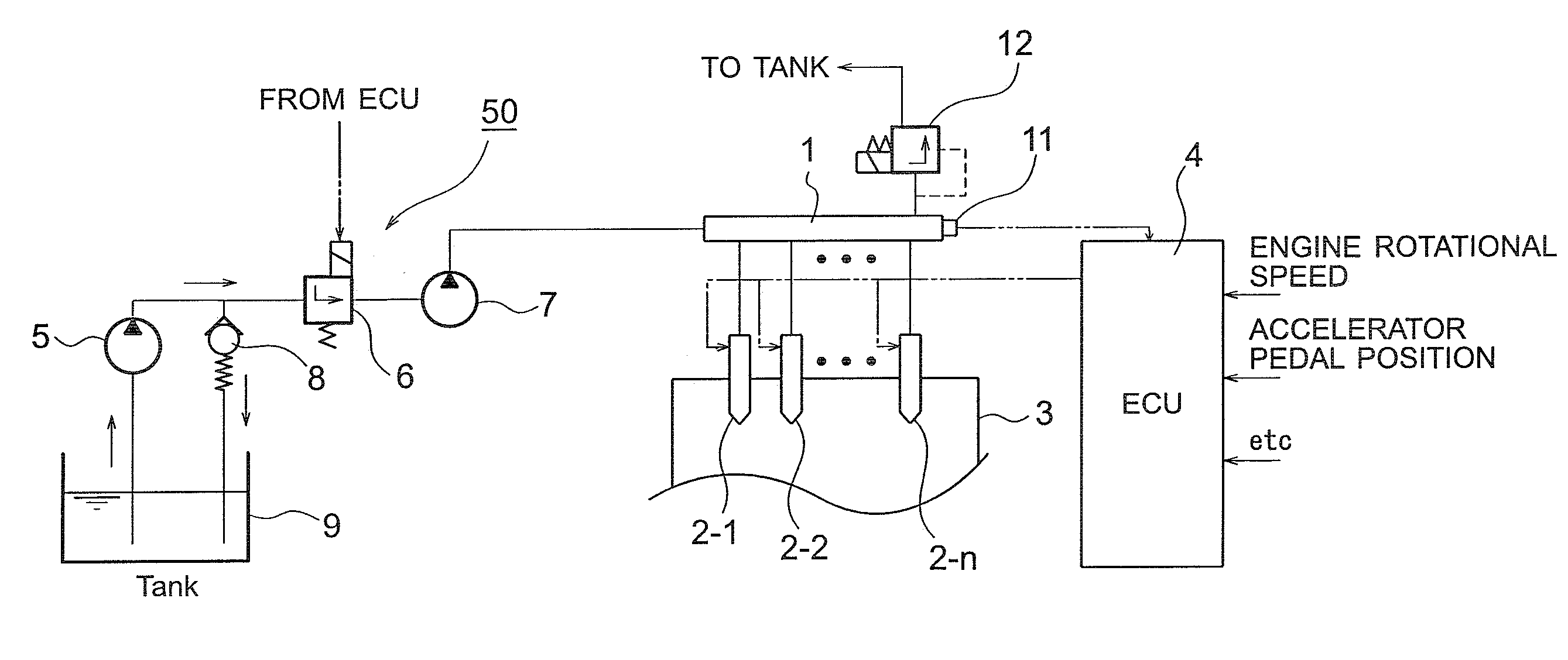
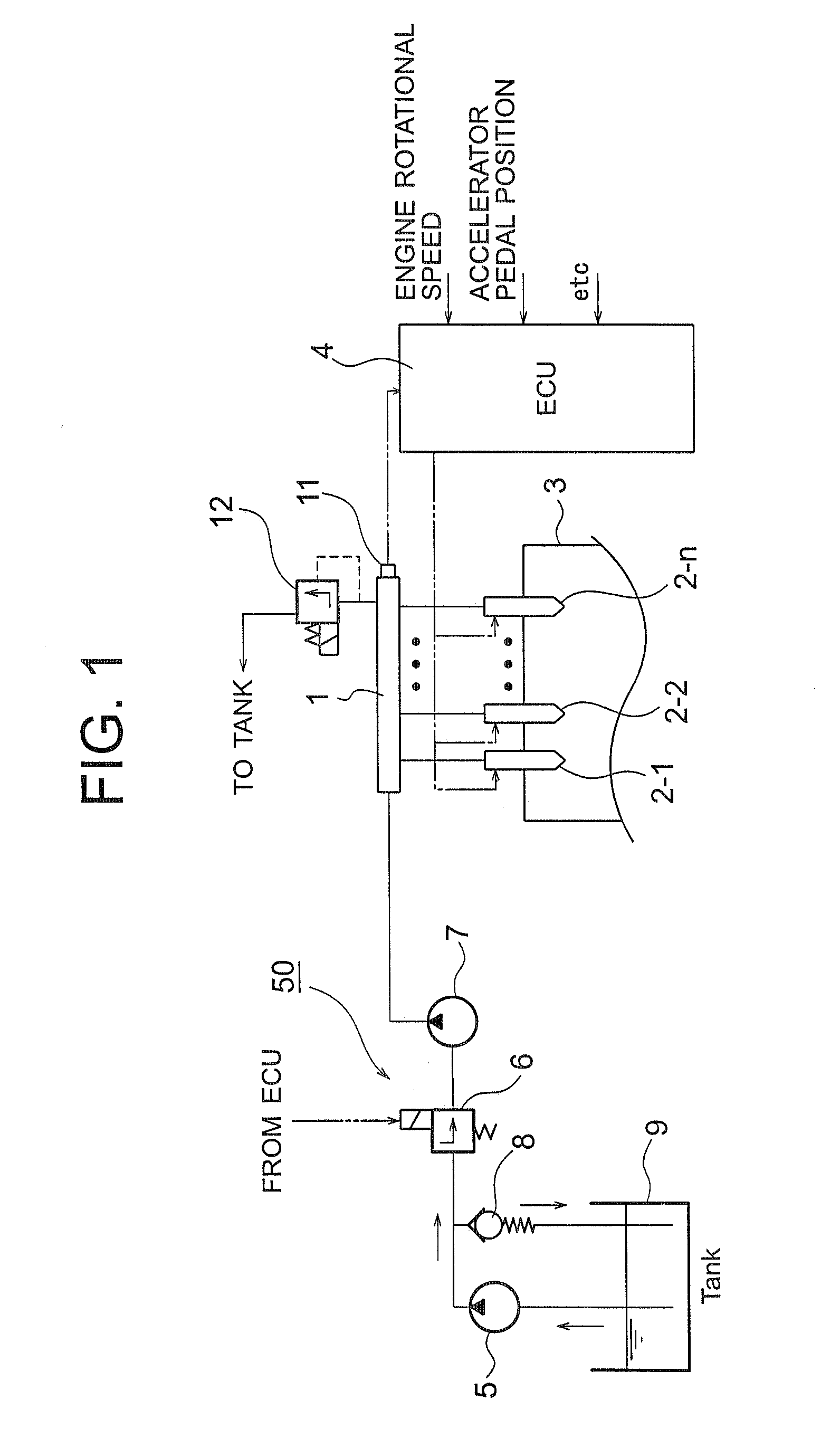
[0028]First, an example of the structure of an internal combustion engine injection control apparatus, to which a failure diagnosis method of a pressure sensor according to the embodiment of the invention is applied, is described with reference to FIG. 1.

[0029]More specifically, the internal combustion engine injection control apparatus shown in FIG. 1 includes, in particular, a common rail type fuel injection control apparatus.

[0030]The main structural elements of the common rail type fuel injection control apparatus are a high pressure pump device 50 that pressure feeds high pressure fuel, a common rail 1 that accumulates the high pressure fuel pressure fed by the high pressure pump de...


PUM


Abstract

It is possible to perform a failure diagnosis of a pressure sensor with a simple structure without installing a dedicated circuit for the failure diagnosis.
In a common rail type fuel injection control apparatus, a pressure control valve 12 is provided in a fuel return path from a common rail 1, and a rail pressure detected by a pressure sensor 11 can be controlled to match a target rail pressure through drive control of the pressure control valve 12 by an electronic control unit 4. The target rail pressure is calculated based on operational information of an engine 3. In the common rail type fuel injection control apparatus, learning processing is performed, in which a correction coefficient Cv is stored and updated as a learning value to correct energization characteristics of a median product of the pressure control valves 12 that are stored in the electronic control unit 4. At the same time, it is determined whether the learning value of the correction coefficient Cv is within a predetermined range. When it is determined that it is not within the predetermined range, the pressure sensor 11 is diagnosed as having a failure.

Description

BACKGROUND OF THE INVENTION[0001]1. Field of the Invention[0002]The present invention relates to sensor failure detection, and it particularly relates to sensor failure detection with improved swiftness, easiness etc.[0003]2. Description of the Related Art[0004]For example, various sensors are provided in an electronic control device of an automobile internal combustion engine, such as a diesel engine, and detection signals of the various sensors are used for operational control of the internal combustion engine.[0005]One example of such a sensor is a pressure sensor that detects rail pressure in a common rail type fuel injection control apparatus. The pressure sensor is important to achieve appropriate fuel injection, and various types of methods have been proposed to detect a failure.[0006]As one of failure diagnosis methods of the pressure sensor in the common rail type fuel injection control apparatus, for example, a method has been proposed in which, when a failure of the press...

Claims


Application Information

Patent Timeline
IPC IPC(8): F02D41/22F02D41/30F02M69/46
CPCF02D41/222F02D41/2464F02D2041/223F02D43/02F02D41/3836
Inventor KANEKO, HIROTAKASUDA, SAKAEIINO, KENICHI
Owner BOSCH CORP
Why Eureka
Try Eureka