Power management apparatus and methods

a power management and power management technology, applied in pulse manipulation, pulse technique, instruments, etc., can solve problems such as system instability, corruption or malfunction, and device complexity and expense, and achieve the effect of improving the complexity and expense of the devi

Active Publication Date: 2011-01-27
CIRRUS LOGIC INC
View PDF17 Cites 114 Cited by
  • Summary
  • Abstract
  • Description
  • Claims
  • Application Information

AI Technical Summary

Benefits of technology

[0027]This embodiment of the present invention is concerned with transitions between various power states of a PMIC and imposes a predetermined delay between receipt of a power state transition command and start of the appropriate power state transition. This predetermined delay allows time for an operating system of the device to correctly terminate any relevant processes, i.e. those involving parts of the system that are being deactivated, prior to the power state transition being enacted by the PMIC. If necessary the predetermined delay may also allow time for the system state to be written to memory.
[0095]In this embodiment of the invention, when the output settings for a first (source) power block are updated, in order to vary the output of the first power block, these settings can be automatically translated for use by a second (destination) power block. Thus the second power block can use the translated output settings and provide a changed output without requiring the output settings for the second power block to be specifically updated by the control circuitry. A second power domain, powered by the second power block, may therefore be arranged to have a voltage level which follows that of a first power domain, powered by the first power block, without any substantial time lag. Thus a serial control interface can be used by the control circuitry to control the power blocks as is conventional and no parallel interfaces or group addressing schemes are required.

Problems solved by technology

One possible problem in applying power state transitions is that, for some electrical devices, the operating system of the device may be running various processes at the time that the power state transition command, i.e. a command for the power management unit to change from its present power state to a different power state, is issued.
Thus an operating system of the device may not be in control over when a power state transition command is issued and may be performing a critical function when the command is issued.
If the power management unit removes power to a critical part of the system, prior to successful termination of the critical processes or completion of a memory storing step this may lead to system instability, corruption or malfunction.
However such handshaking arrangements typically require relatively complex hardware, which adds to the complexity and expense of the device, and may not be fully effective as the operating system needs to be active to some extent to perform the handshaking itself so not everything can be terminated.
This increases power consumption and reduces battery life compared to removing power from all non-functional device systems.

Method used


Image

  • Power management apparatus and methods
  • Power management apparatus and methods
  • Power management apparatus and methods

Examples


Embodiment Construction

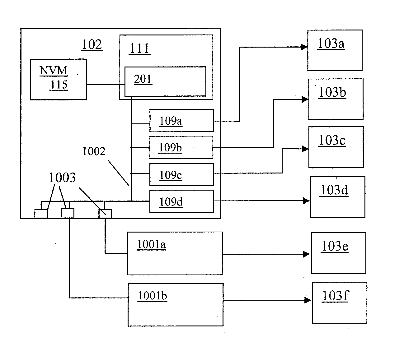
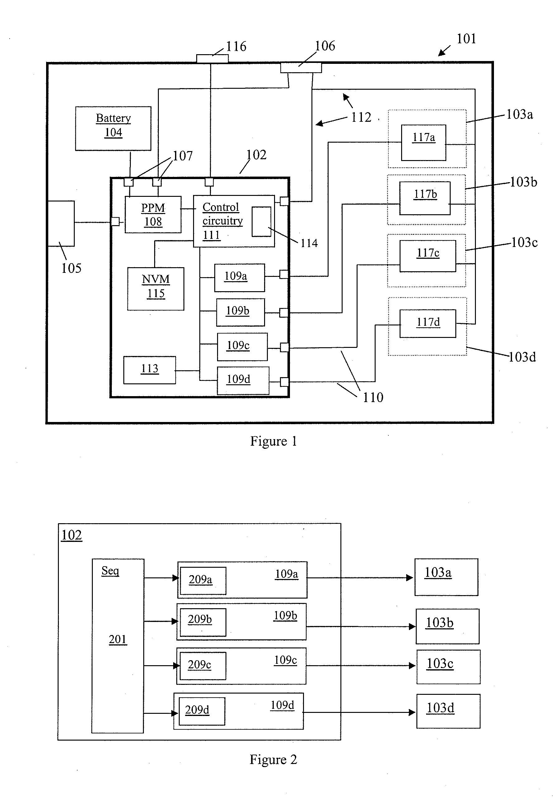
[0147]FIG. 1 illustrates the general principles of the power supply and power management in a device, generally indicated 101, which may, for instance, be a portable device. The device 101 includes a power management integrated circuit (PMIC) 102 for managing power supply to the device. The PMIC receives power from various possible power sources and regulates the power supply to the various power domains 103a-d of the device. In this example the device has three possible power sources. There is an internal battery 104 for supplying power when other power sources are not available. The device also has a bulk power interface 105 adapted to receive bulk power, i.e. an interface that is designed to operate with equipment allowing the device 101 to be plugged into a socket delivering mains electricity, e.g. a wall socket in the home. For portable devices the bulk interface is typically designed to interface with an external adapter that plugs into the bulk supply and converts the AC supp...


PUM


Abstract

Power management integrated circuits (PMICs) and related methods. In one aspect a PMIC which is operable to provide a plurality of PMIC power states is arranged to provide a predetermined delay before a power state transition. The delay is applied after receipt by the PMIC control circuitry of a power state transition command. Applying a delay allows time for the system powered by the PMIC to perform any necessary shut-down procedures and terminate active processes before power is removed, preventing corruption of the system. The delay is preferably configurable. The PMIC may also be arranged to control power converters which are external to the PMIC. In another aspect the PMIC has translation circuitry for providing the control settings of one power block, e.g. power converter, with any necessary modifications to be used by another power block. This means that only one set of control settings needs to be updated to change the output of both power blocks simultaneously.

Description

[0001]This application claims the benefit of U.S. Provisional Application No. 61 / 227,947, filed Jul. 23, 2009.BACKGROUND OF THE INVENTION[0002]1. Field of the Invention[0003]This invention relates to the field of power management and power management apparatus, in particular power management integrated circuits, for supplying and regulating power to electrical devices, in particular to portable electrical devices.[0004]2. Description of the Related Art[0005]Many electrical devices include some sort of power management functionality. A power management unit, which is typically a power management integrated circuit (PMIC), is typically arranged to receive power from a power supply, which may be one of a plurality of possible power supplies, and provide appropriately controlled and regulated power to one or more power domains within the device in response to the power requirements thereof. As used in this specification the term “device” is used to refer to an electrical product, for ex...

Claims


Application Information

Patent Timeline
Patent Type & Authority Applications(United States)
IPC IPC(8): G06F1/26H02J4/00H03H11/16
CPCG06F1/3203
Inventor MORE, GRANT M.HAIPLIK, HOLGER
Owner CIRRUS LOGIC INC
Why Eureka
Try Eureka