CsLiLn HALIDE SCINTILLATOR

a technology of halide scintillator and composition, which is applied in the direction of photometry using electric radiation detectors, optical radiation measurement, instruments, etc., can solve the problems of difficult prediction of actual use of scintillator spectrometer and various practical applications, and the inability to meet the requirements on the whole by many commercially available scintillator compositions. achieve good energy resolution

Active Publication Date: 2011-02-03
RADIATION MONITORING DEVICES
View PDF7 Cites 33 Cited by
  • Summary
  • Abstract
  • Description
  • Claims
  • Application Information

AI Technical Summary

Benefits of technology

[0012]Excellent scintillation properties, including high light output, good proportionality, response, and good energy resolution have been measured for certain compositions of the present invention. Scintillator compositions of the present invention have demonstrated emission characteristics indicating suitability for use in various applications. For example, scintillation properties of the compositions can include peak emission wavelengths from about 380 nm, which is well matched to PMTs as well as silicon diodes used in nuclear instrumentation and a peak wavelength for gamma-ray spectroscopy.

Problems solved by technology

These requirements on the whole cannot be met by many of the commercially available scintillator compositions.
While general classes of chemical compositions may be identified as potentially having some attractive scintillation characteristic(s), specific compositions / formulations having both scintillation characteristics and physical properties necessary for actual use in scintillation spectrometers and various practical applications have proven difficult to predict.
Specific scintillation properties are not necessarily predictable from chemical composition alone, and preparing effective scintillator compositions from even candidate materials often proves difficult For example, while the compositions of sodium chloride and sodium iodide had been known for many years, the invention by Hofstadter of a high light-yield and conversion efficiency scintillator from sodium iodide doped with thallium launched the era of modern radiation spectrometry.
With the advent of X-ray CT in the 1970's, a major commercial field emerged as did a need for different scintillator compositions, as NaI(T1) was not able to meet the requirements of CT imaging.
As the methodology of scintillator development evolved, new materials have been added, and yet, specific applications are still hampered by the lack of scintillators suitable for particular applications.

Method used


Image

  • CsLiLn HALIDE SCINTILLATOR
  • CsLiLn HALIDE SCINTILLATOR
  • CsLiLn HALIDE SCINTILLATOR

Examples


Embodiment Construction

[0027]This invention will be better understood with resort to the following definitions:

[0028]A. Rise time, in reference to a scintillation crystal material, shall mean the speed with which its light output grows once a gamma-ray has been stopped in the crystal. The contribution of this characteristic of a scintillator contributes to a timing resolution.

[0029]B. A Fast timing scintillator (or fast scintillator) typically requires a timing resolution of about 500 ps or less. For certain PET applications (e.g., time-of-flight (TOF)), the fast scintillator should be capable of localizing an annihilation event as originating from within about a 30 cm distance, i.e., from within a human being scanned.

[0030]C. Timing accuracy or resolution, usually defined by the full width half maximum (FWHM) of the time of arrival differences from a point source of annihilation gamma-rays. Because of a number of factors, there is a spread of measured values of times of arrival, even when they are all eq...


PUM


Abstract

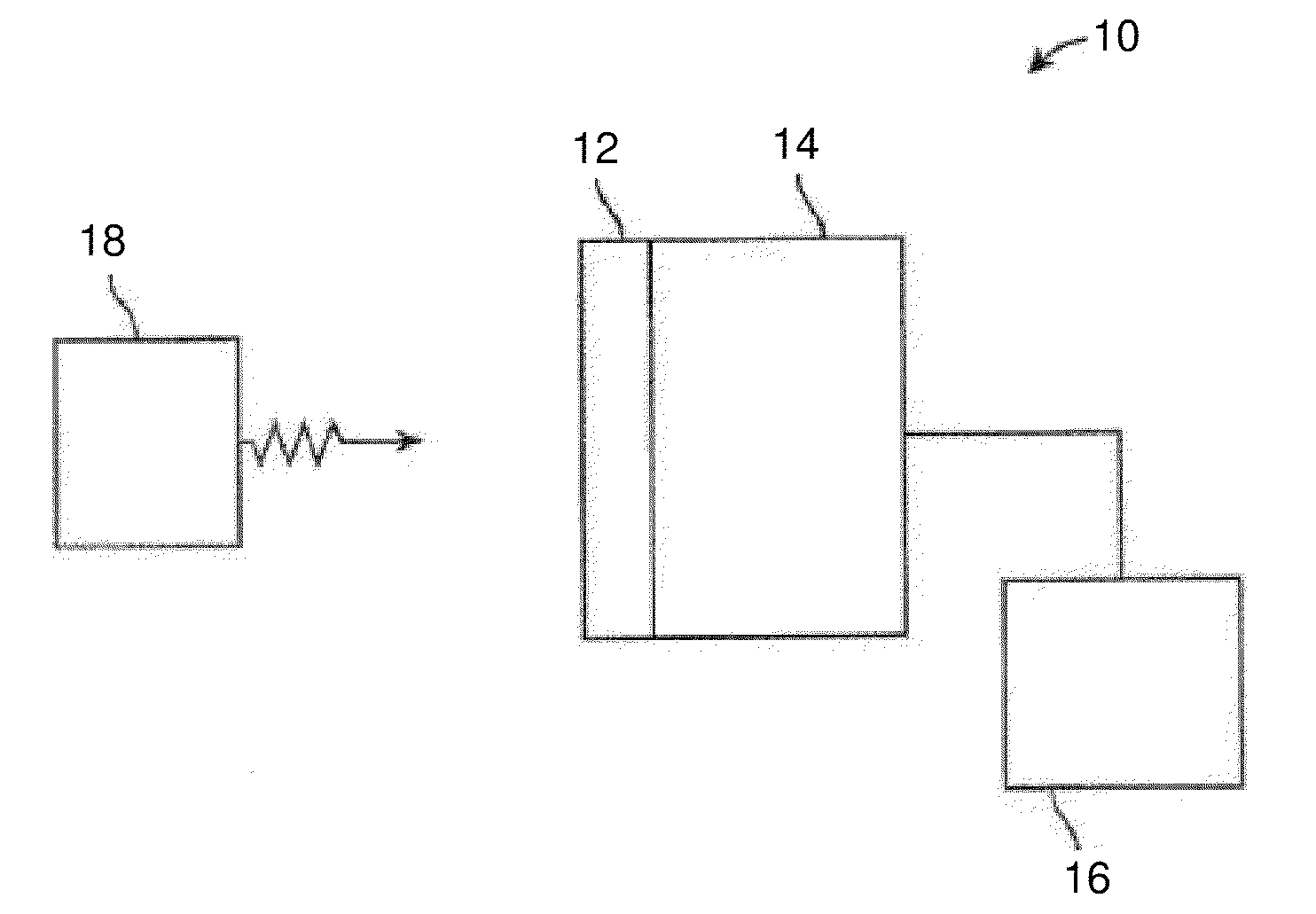
Li-containing scintillator compositions, as well as related structures and methods are described. Radiation detection systems and methods are described which include a Cs2LiLn Halide scintillator composition.

Description

CROSS REFERENCE TO RELATED APPLICATIONS[0001]The present application is a continuation-in-part application of U.S. patent application No., entitled “Enriched CsLiLn Halide Scintillator”, by Shah et al., filed on Nov. 23, 2009 which is incorporated herein by reference in its entirety and claims the benefit of priority under 35 U.S.C. §119(e) of U.S. Provisional Application No. 61 / 230,970, filed Aug. 3, 2009 which is also incorporated herein by reference in its entirety.BACKGROUND OF THE INVENTION[0002]The present invention relates to scintillator compositions and related devices and methods. More specifically, the present invention relates to enriched Li-containing scintillator compositions suitable for use, for example, in radiation detection, including gamma-ray spectroscopy, and X-ray and neutron detection.[0003]Scintillation spectrometers are widely used in detection and spectroscopy of energetic photons (e.g., X-rays, gamma-rays, etc.). Such detectors are commonly used, for exam...

Claims


Application Information

Patent Timeline
Patent Type & Authority Applications(United States)
IPC IPC(8): G01T3/06G01T1/20
CPCG01T1/202G01T3/06C09K11/7733C09K11/7773G01T1/2006C30B11/00C30B15/00C30B29/12C09K11/778C09K11/7705C09K11/772C09K11/7791C01F17/271G01T1/2023
Inventor SHAH, KANAI S.HIGGINS, WILLIAM M.VAN LOEF, EDGAR V.GLODO, JAROSLAWHAWRAMI, RASTGOSHIRWADKAR, URMILA
Owner RADIATION MONITORING DEVICES
Why Eureka
Try Eureka