System and method of testing high brightness LED (HBLED)

Inactive Publication Date: 2011-02-03
DODDS STANLEY CURTIS JR
View PDF36 Cites 38 Cited by
  • Summary
  • Abstract
  • Description
  • Claims
  • Application Information

AI Technical Summary

Benefits of technology

[0011]While both traditional and Controlled Energy Testing methods or strategies will allow measurement of the same properties of the devices, Controlled Energy Testing methods or strategies are better aligned to fit the true nature of the devices as well as the type of application in which the devices will be used. The Controlled Energy Testing methods or strategies improve the accuracy and, more importantly, the repeatability of the measurements without sacrificing the speed of the test.

Problems solved by technology

First, because traditional HBLED test systems are optimized to force current and measure voltage, the actual amount of power being sent to a HBLED DUT is not monitored, and is therefore unknown.
Further, because traditional HBLED test system implementations do not provide precise control over the timing of all aspects of a test sequence, the precise amount of energy delivered to the DUT (power*time) cannot be determined either.
Because of the uncertainty in the amount of power delivered to the DUT and the uncertainty in the timing of test and measurement sequences, the accuracy and repeatability of measured results are compromised and measured data will vary from test to test.

Method used


Image

  • System and method of testing high brightness LED (HBLED)
  • System and method of testing high brightness LED (HBLED)
  • System and method of testing high brightness LED (HBLED)

Examples


Embodiment Construction

[0017]In one embodiment of the present invention, Controlled Energy Testing is implemented whereby the Controlled Energy Testing is a method for improving the accuracy and repeatability of measurements taken during the course of performing parametric and / or functional testing of electronic or optoelectronic devices.

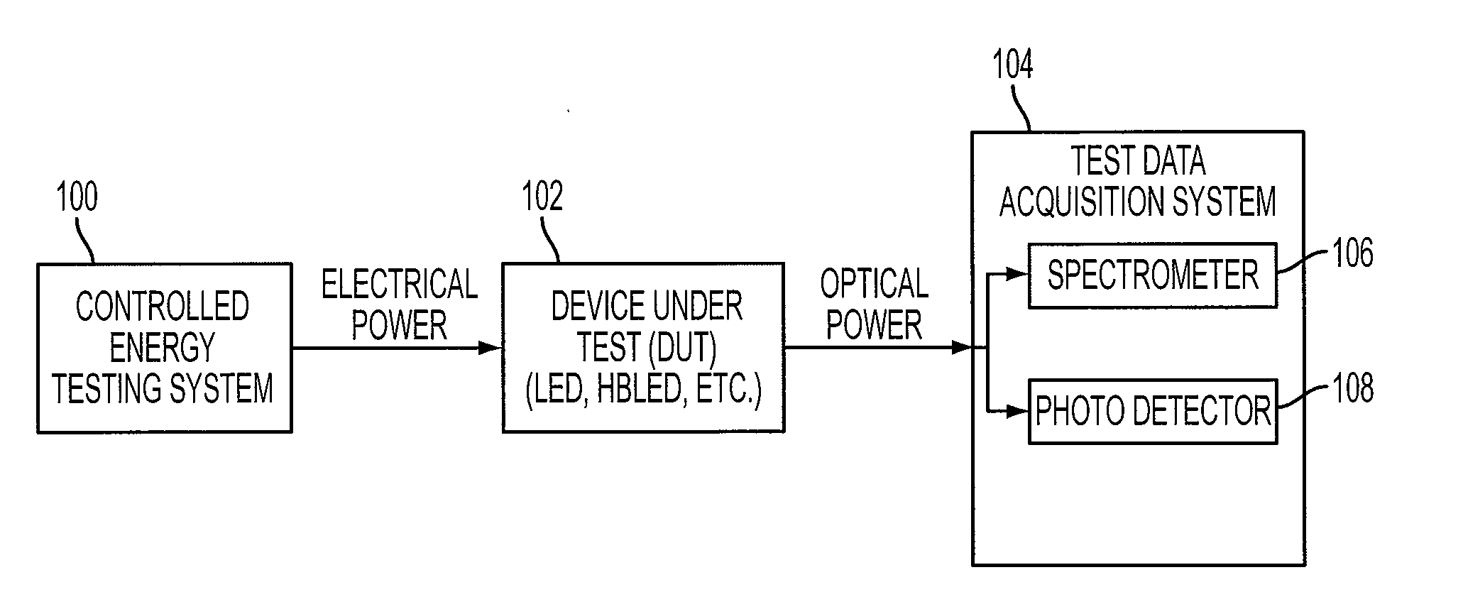
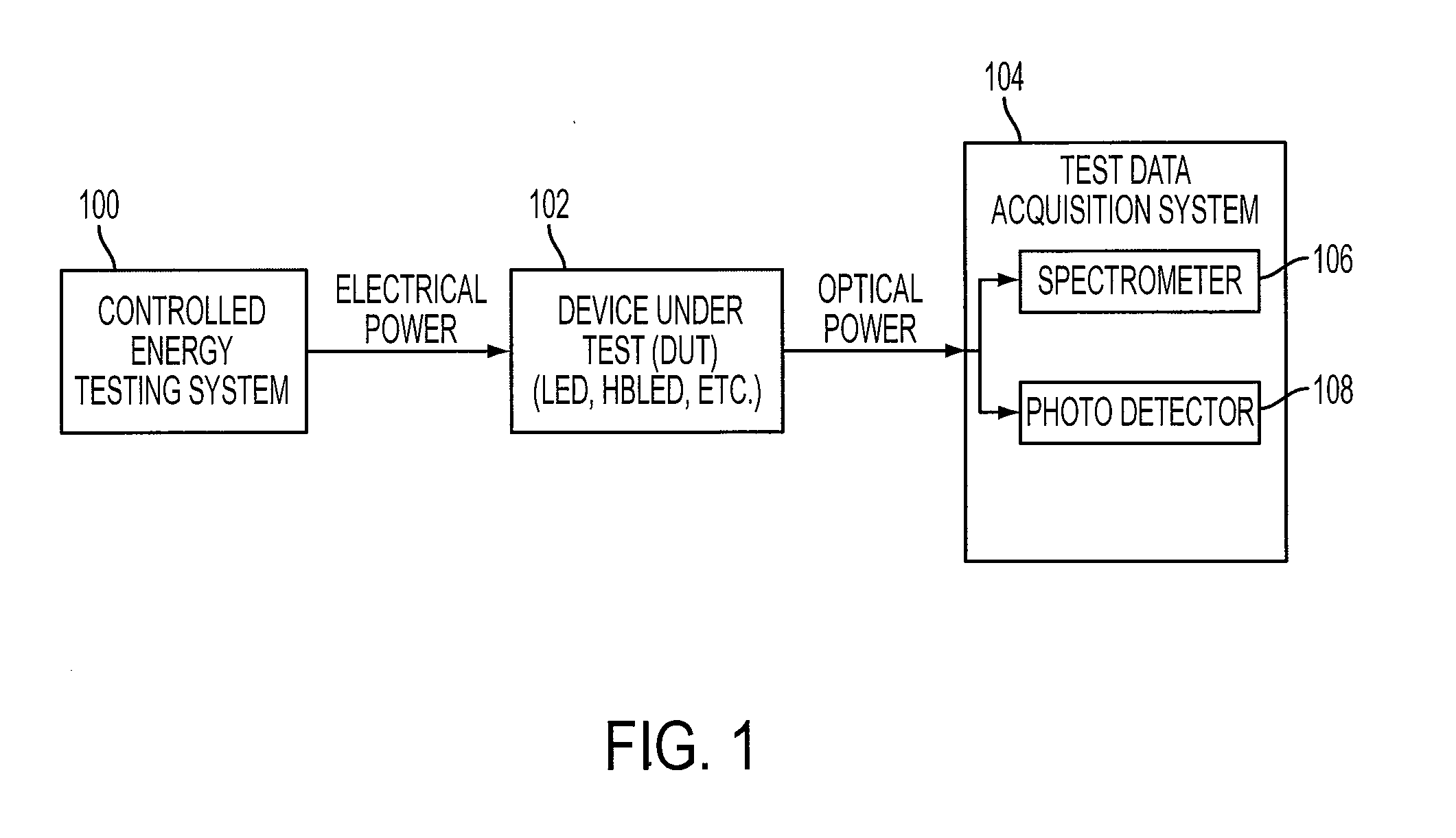
[0018]The Controlled Energy Testing technique uses a programmable constant power source in conjunction with precise timing circuits to deliver a given or predetermined amount of power to a Device Under Test (DUT) for a predetermined amount of time, while coordinating timing of acquisition of various parametric data.

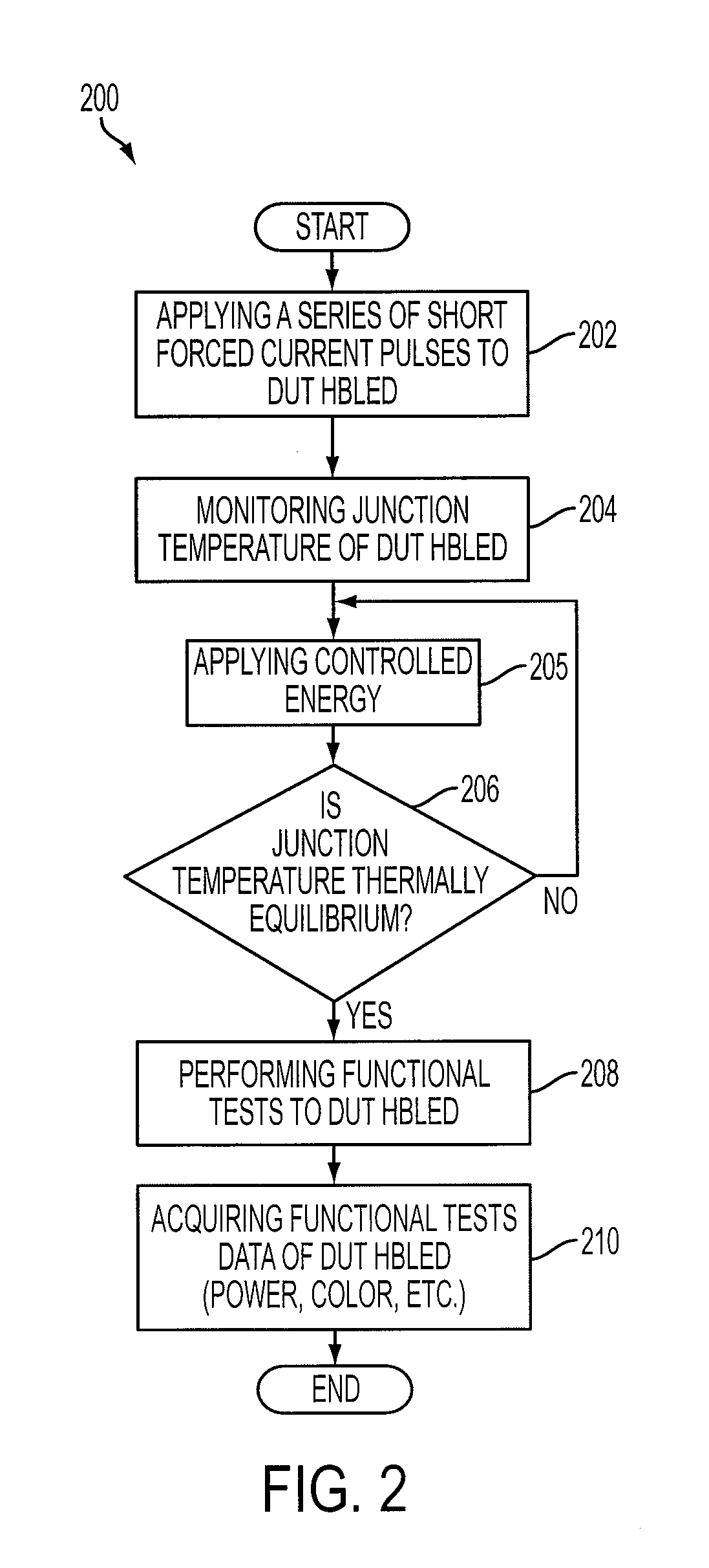
[0019]FIGS. 1 and 2 illustrate a system and method of a Controlled Energy Testing system 100 and method 200 for a DUT HBLED. The implementation of the Controlled Energy Testing system and method, e.g. a Controlled Energy Testing Parametric Measurement Unit (PMU) 300 (diagrammed in FIG. 3) is based on an analog parametric measurement unit controlled by a network...


PUM


Abstract

A system and method of testing High Brightness LED (HBLED) is provided, and more particularly, a system and method of Controlled Energy Testing of HBLED with improved accuracy and repeatability is provided. In one embodiment, the system includes a programmable constant power source for providing a constant power to a Device Under Test (DUT), in this case, an HBLED, wherein the programmable constant power source adjusts an output voltage or an output current to ensure that a given amount of power is supplied to the HBLED for a predetermined amount of time and to provide precise control of a junction temperature of the HBLED for the duration of the test sequences; a Parametric Measurement Unit (PMU) including a processor for executing a plurality of HBLED test sequences, and a spectrometer for measuring a set of HBLED parameters including power and color (wavelength) of an optical output of the HBLED; and a controller for coordinating timing of acquiring the set of measured HBLED parameters. In another embodiment, a photodetector is implemented to measure the integrated power of the optical output of the HBLED.

Description

CROSS-REFERENCE TO RELATED APPLICATION(S)[0001]The present utility patent application claims priority of U.S. Provisional Patent Application Ser. No. 61 / 230,968, filed Aug. 3, 2009; subject matter of which is incorporated herewith by reference.FIELD OF THE INVENTION[0002]The present invention relates generally to a system and method of testing solid state light emitting devices such as High Brightness Light Emitting Diodes (HBLED), and more particularly, to a system and method of controlled energy testing of HBLED with improved accuracy and repeatability of measurement.BACKGROUND OF THE INVENTIONHistory of Light Emitting Diodes (LED)[0003]The earliest records of scientific observation of the luminescence of forward-biased diodes began in 1907 with the discovery of the LED. This invention was widely credited to the Russian technologist Oleg Vladimirovich Losev, who observed that zinc oxide and silicon carbide diodes used in the receiver circuits of radio sets he was working with emit...

Claims


Application Information

Patent Timeline
IPC IPC(8): G01R31/00
CPCG01R31/2635G01R31/26
Inventor MORROW, DANIEL CREIGHTONDUMMER, JONATHAN LEIGH
Owner DODDS STANLEY CURTIS JR
Why Eureka
Try Eureka