Supercharge Your Innovation With Domain-Expert AI Agents!

Control system and a method for information display systems for vehicles on cross roads

Inactive Publication Date: 2011-02-03
REJALI MOHAMMADREZA +1
View PDF9 Cites 6 Cited by
  • Summary
  • Abstract
  • Description
  • Claims
  • Application Information

AI Technical Summary

Benefits of technology

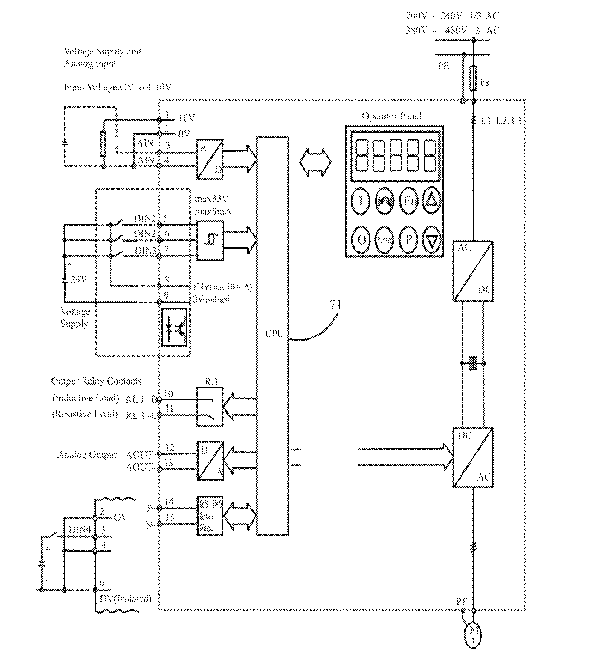
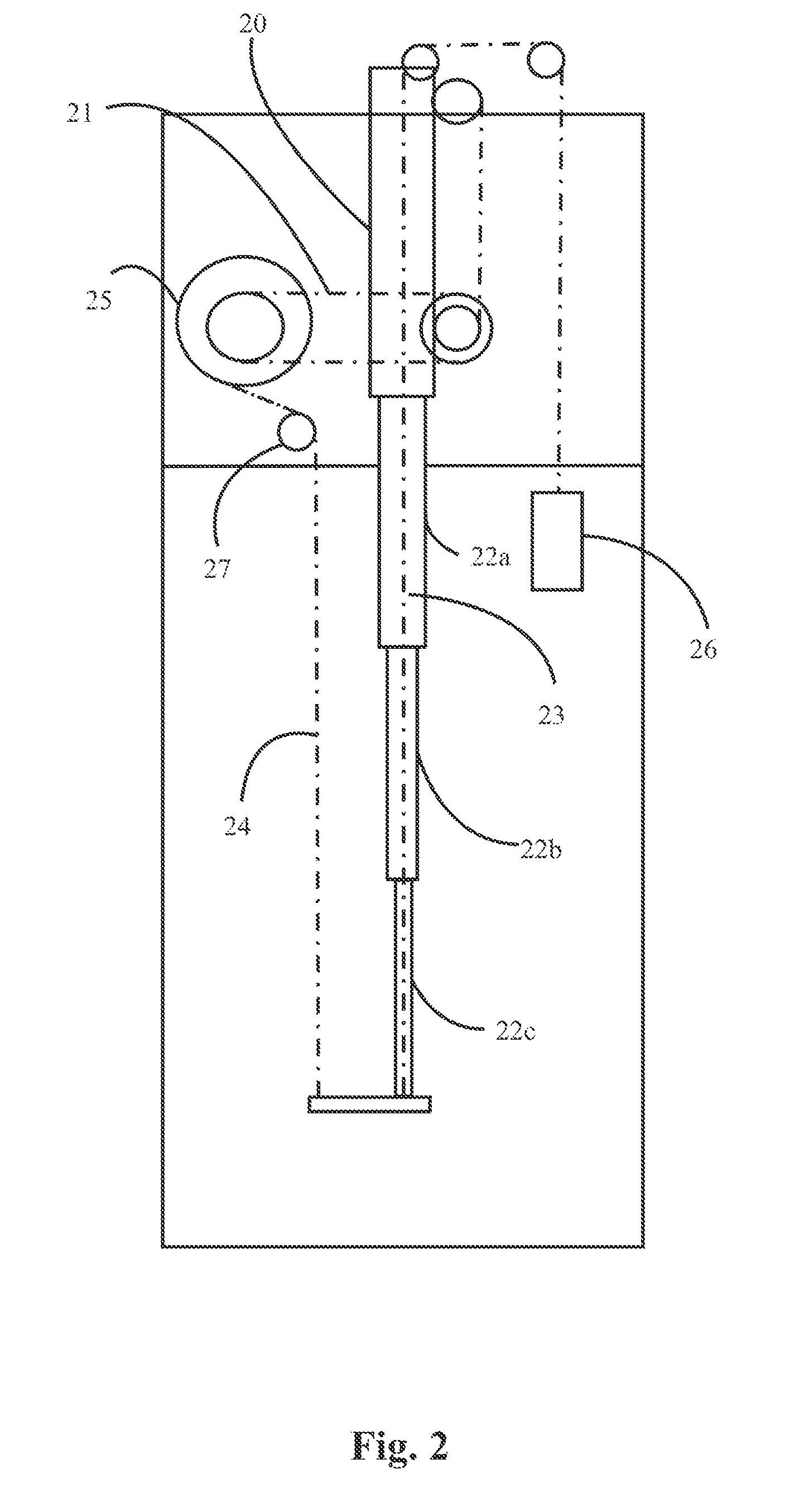
[0021]During the upward or downward motion of the panel, a mechanical power is transmitted from the magnetic coupler and the chain type transmission arrangement to the drum and to the telescopic arms for vertical motion. A counterweight arrangement is provided in the movement control mechanism for the upward movement of the panel during the electric power interruption period. A tensioner is provided in the movement control mechanism for reducing an extra length and shortening of the fabric panel caused during the downward movement of the fabric panel. An AC drive is provided for controlling the speed of the electric motor and to prevent a shock during start and stop condition of the movement control mechanism. The PLC along with the sensors and the AC drive are embedded in a steel control panel. The fabric panel along with the two telescopic arms move downwards upon reception of a yellow light signal from the other side of the cross road and the fabric panel along with the two telescopic arms move upwards upon reception of succeeding yellow light signal from the other side of the cross road.

Problems solved by technology

Often, drivers get stuck in their vehicles and spend a lot of time during red light at traffic signals, along a drive during ones day.
Moreover, there is no communication system to deliver effective information related to medicine, arts, science, cultural, traffics, advertisement and other aspects to the society.
Yet in another existing scheme, a traffic information media disturbs the driver's concentration during driving thereby increasing the chances of the drivers to meet with an accident and is less effective.

Method used


Image

  • Control system and a method for information display systems for vehicles on cross roads
  • Control system and a method for information display systems for vehicles on cross roads
  • Control system and a method for information display systems for vehicles on cross roads

Examples


Embodiment Construction

[0009]The primary object of the embodiments herein is to provide a control system and method for displaying information to vehicle users while the vehicles are at cross roads.

[0010]Another object of the embodiments herein is to provide a control system and the method for employing a mass media during red light period in cross roads for advertising general information and traffic regulatory information.

[0011]Yet another object of the embodiments herein is to provide an information display control system and method for delivering effective information related to medicine, arts, science, cultural, traffics, advertisement and other aspects to the society.

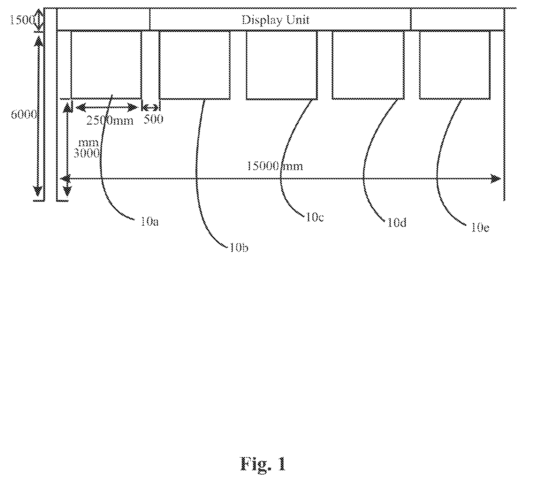
[0012]Yet another object of the embodiments herein is to provide an information display control system and method including at least one of a fabric panel or a LCD panel designed for delivering traffic regulatory information and installed at higher elevation in front of the cross road for clear visibility.

[0013]Yet another object of the...


PUM


Abstract

The various embodiments herein provide a system and method for managing information display for vehicles on cross roads. The system includes at least one panel to display a traffic regulatory information and advertisements, a central server, a programmable logic controller (PLC) connected to the central server, a plurality of sensors to detect the at least one panel position and any moving foreign objects. A display unit is managed online from a traffic control centre to receive and display a real-time traffic information and a plurality of timers are provided for calculating a time schedule information of the traffic lights based on the traffic. The sensors control and transmit the time schedule information to the PLC. The time schedule information and traffic algorithms are transmitted by the PLC to a central control system for processing and estimating an optimum time schedule of traffic lights.

Description

CROSS-REFERENCE TO RELATED APPLICATION[0001]This application claims the priority under 35 USC 119(e) of U.S. Provisional Application Ser. No. 61 / 309,441, which is included by reference herein.BACKGROUND[0002]1. Technical Field[0003]The embodiments herein generally relate to information display systems and methods and particularly to a control system and method for managing the display of information for vehicles on cross roads. The embodiments herein more particularly relates to a control system and the method for employing a mass media in use during red light period in cross roads for displaying advertisements and traffic regulatory information.[0004]2. Description of the Related Art[0005]Often, drivers get stuck in their vehicles and spend a lot of time during red light at traffic signals, along a drive during ones day. It is common for the drivers to wait for a long period of time on the red light even when there is little or no traffic flow from opposite or adjacent direction of...

Claims


Application Information

Patent Timeline
IPC IPC(8): G08G1/09E01F9/646
CPCE01F9/0113G08G1/0175G08G1/08G08G1/096783G08G1/095G08G1/096G08G1/096733G08G1/09E01F9/696
Inventor REJALI, MOHAMMADREZATAVANAEI POOYA, MOJTABA
Owner REJALI MOHAMMADREZA
Features
  • R&D
  • Intellectual Property
  • Life Sciences
  • Materials
  • Tech Scout
  • Unparalleled Data Quality
  • Higher Quality Content
  • 60% Fewer Hallucinations
Learn More