Surface Mapping by Optical Manipulation of Particles in Relation to a Functionalized Surface

Active Publication Date: 2011-02-03
ARRYX INC
View PDF23 Cites 13 Cited by
  • Summary
  • Abstract
  • Description
  • Claims
  • Application Information

AI Technical Summary

Benefits of technology

[0039]Optionally, or in addition, all the components are carried on a mobile structure. The system may also include at least one feature selected from the group consisting of an inte

Problems solved by technology
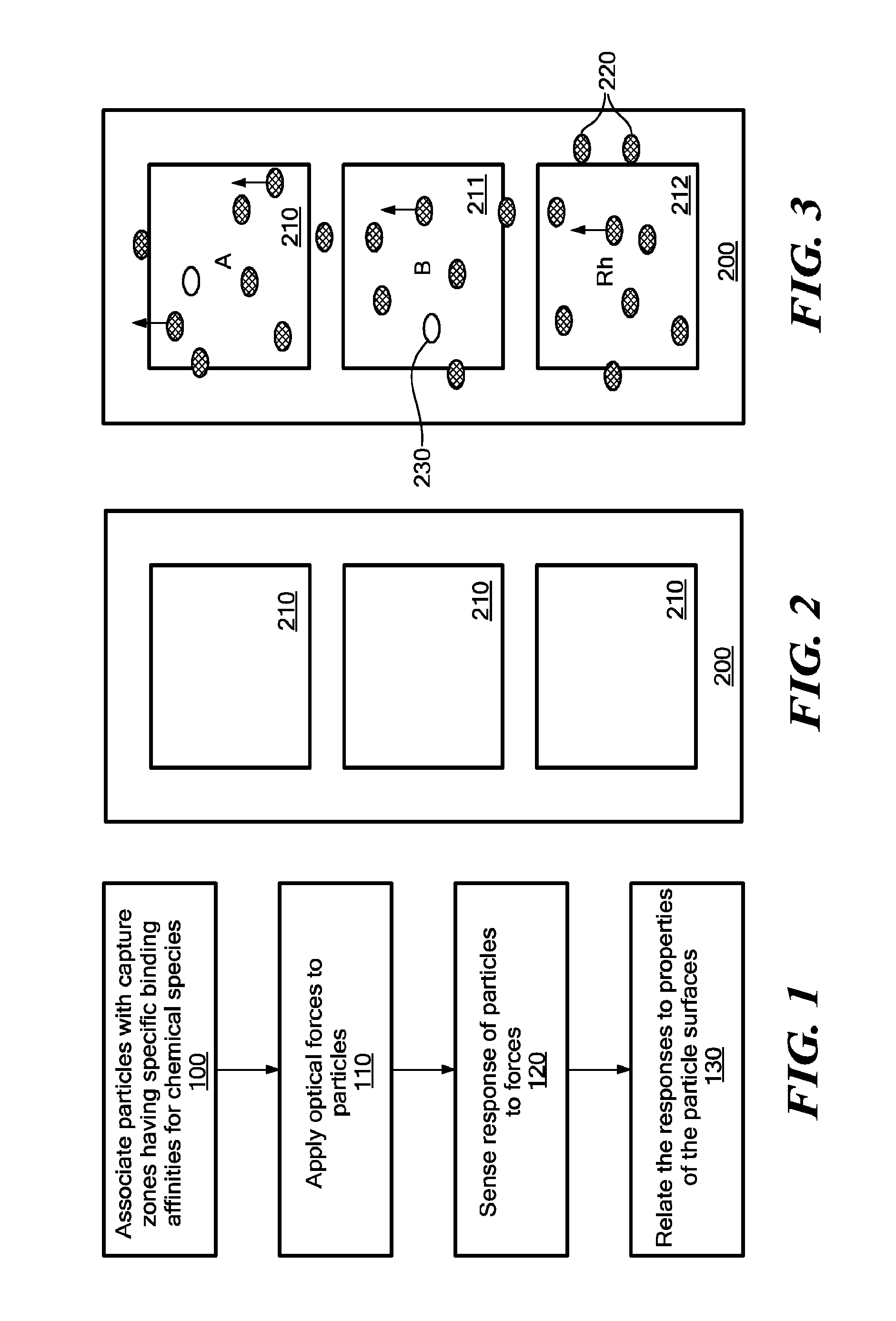
A major limitation for conventional arrays is that long incubation times are usually required to reach a state of binding that is sufficiently close to equilibrium to allow useful analysis.
Such delays can cause added expense, preclude use in emergency situations, and reduce data quality due to degradation of reagents during the protracted incubation times. Other limitations of conventional approaches is the need for analyte labeling steps and stringent washing steps, which introduce additional costs in terms of labor and equipment, and may impact data quality.
As is known in the art, red blood cells (“RBCs”) from different patients

Method used


Image

  • Surface Mapping by Optical Manipulation of Particles in Relation to a Functionalized Surface
  • Surface Mapping by Optical Manipulation of Particles in Relation to a Functionalized Surface
  • Surface Mapping by Optical Manipulation of Particles in Relation to a Functionalized Surface

Examples


example 1

Blood Typing Analysis Using Automated Microscopy and Optical Forcing

[0147]The user opens the sample door and places the sample chip inside. The user closes the door and presses “Begin Test” on the touch screen. The objective lens, and hence image plane, starts out far lower (1 mm or so) than the bottom of the cartridge cover (a coverslip). The microscope stage moves to its limits to find them and then moves to the position that should correspond to the center of the first capture zone on the sample chip. The software turns on a red autofocus laser and directs the focus knob to rotate, raising the objective lens by 100 um / s or more. The camera images are observed until the system senses a flash of red indicating reflection of the laser off the bottom surface of the coverslip. A suitable algorithm is used to determine when the laser reflection is at its peak. The autofocus laser then switches off, a green LED illumination is turned on, and the objective lens is adjusted so that the i...


PUM


Abstract

Methods and apparatus for analyzing surface properties of particles are provided. A method for analyzing the surface properties of the particle includes a associating a first particle with a first capture zone having a specific binding affinity for a first chemical species, applying an optical force to the first particle, sensing a response of the first particle to the optical force, and using the sensed response to determine the presence, absence or quantity of the first chemical species on the first particle surface. This process may be repeated in parallel to test multiple particles. In addition to directly testing the surface properties of the particles, the method can be used in direct, indirect and competitive assays to determine the presence, absence or quantity of free or immobilized analytes. A fluidic cartridge with capture zones having avidities that are tuned for the use of optical forces is provided. A software routine for performing the method is also provided.

Description

CROSS REFERENCE TO RELATED APPLICATIONS[0001]This patent application claims priority from U.S. Provisional Patent Application Ser. No. 60 / 844,911 for “Determination of antigen-antibody attachment for protein assay and blood typing by manipulation of multiple bodies within an optically defined potential” filed 15 Sep. 2006; U.S. Provisional Patent Application Ser. No. 60 / 844,890 for “Substrate Functionalization for Blood Typing” filed 15 Sep. 2006; U.S. Provisional Patent Application Ser. No. 60 / 844,910 for “Analytical cartridge for optical manipulation” filed on 15 Sep. 2006; U.S. Provisional Patent Application Ser. No 60 / 844,763 for “Compact sample testing apparatus incorporating holographic optical trapping” filed 15 Sep. 2006; and U.S. Provisional Patent Application Serial No. 60 / 931,451 for “Analytical cartridge for blood typing” filed May 22, 2007. All of the aforementioned Provisional Patent Applications are hereby incorporated by reference herein in their entirety.TECHNICAL F...

Claims


Application Information

Patent Timeline
IPC IPC(8): G01N33/48G01B11/30
CPCG01N33/80G01N33/54373G01N33/48
Inventor KNUTSON, CHRISTOPHERDUKE, CRYSTALSTACEY, GARYMUETH, DANTANNER, EVANAKCAKIR, OSMANFU, HAOJUNLANCELOT, ROBERTCHAKRABARTY, TANIABRADLEY, KENNETH
Owner ARRYX INC
Why Eureka
Try Eureka