
Light source device

a light source and laser light technology, applied in the direction of instruments, photomechanical equipment, active medium materials, etc., can solve the problems of short lighting life cycle, large cost, inability to meet the needs of lighting, etc., and achieve the effect of reducing the lighting life cycle and maintaining stably

Active Publication Date: 2011-02-03
ENERGETIQ TECH
View PDF5 Cites 9 Cited by
  • Summary
  • Abstract
  • Description
  • Claims
  • Application Information

AI Technical Summary

Benefits of technology

The present invention provides a light source device that can stably maintain a high-temperature plasma state and a stable light emission without emitting a large power laser beam. This is achieved by using a pulsed laser beam and a continuous-wave laser beam in a light emission tube. The high-temperature plasma state is generated by the pulsed laser beam and maintained by the continuous-wave laser beam. The light source device can be constituted by a light emission tube, a pulsed laser oscillator part, and a continuous-wave laser oscillator part. The light path of the beams from these parts is superposed in the light emission tube, ensuring the regions with a high-energy state are placed on top of each other. This allows for a reliable formation of the high-temperature plasma state and a stable discharge. The use of a small-output laser oscillator part for both the pulsed and continuous-wave laser beams helps to stabilize the device and suppress interruptions of the high-temperature plasma state.

Problems solved by technology

(a) As in the case of a pulsed laser beam the lighting is started by ‘oscillating a pulsed laser beam having sufficient intensity for the discharge excitement of the enclosed gas’, the laser beam is radiated towards the enclosed gas intermittently, as is shown in FIG. 18(a), because of which the high-temperature plasma state may become interrupted with the interruption of the laser light and it is difficult to maintain the high-temperature plasma state at all times. In other words, there is the problem that the discharge maintenance is instable.
In other words, there is the problem that the lighting life cycle is short.
Further, the power of the laser light necessary to start the discharge amounts from some ten to some hundred kW, but a laser device continuously outputting laser light with such a high output is large and costly and therefore impractical.

Method used


Image

  • Light source device
  • Light source device
  • Light source device

Examples


first embodiment

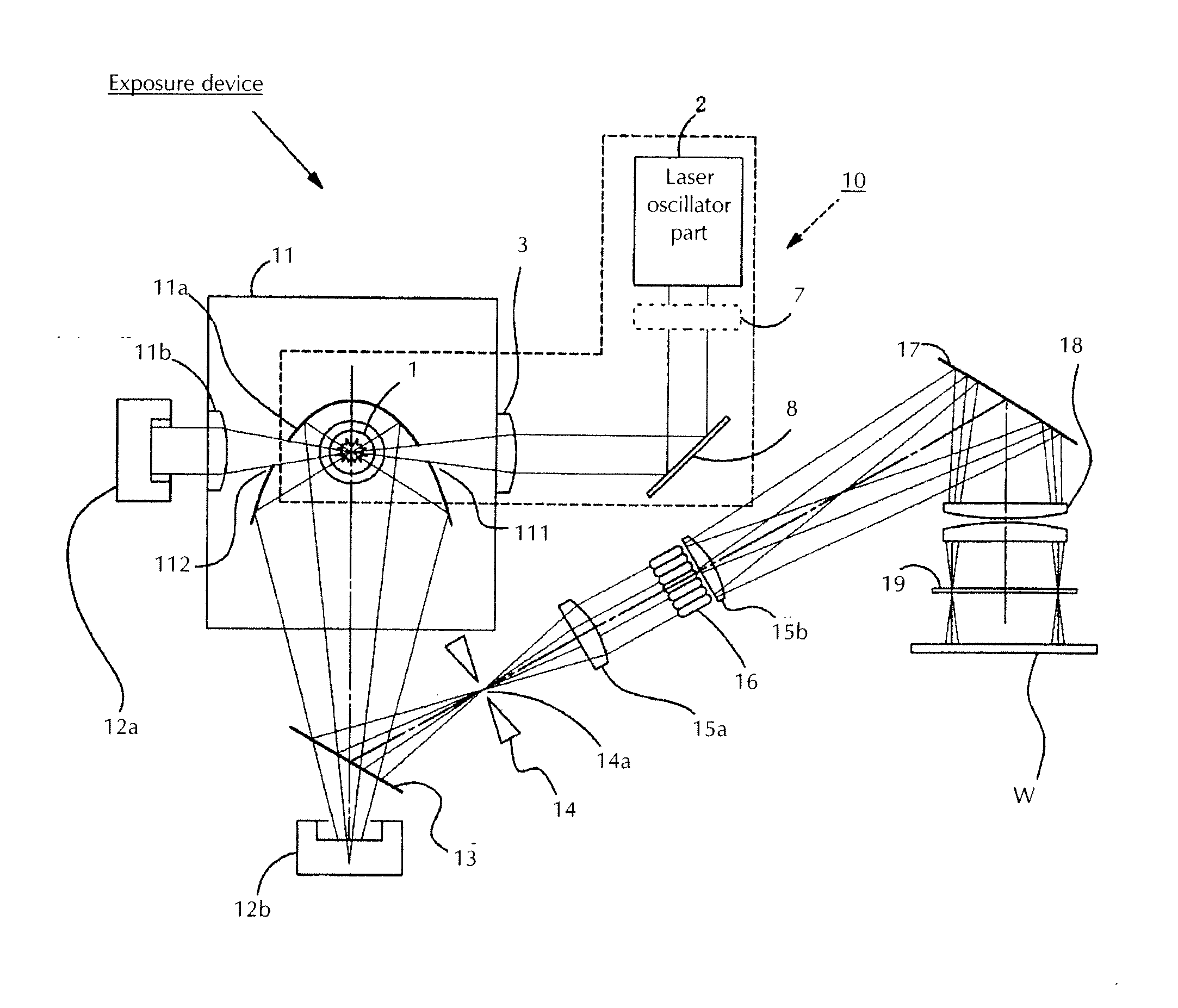
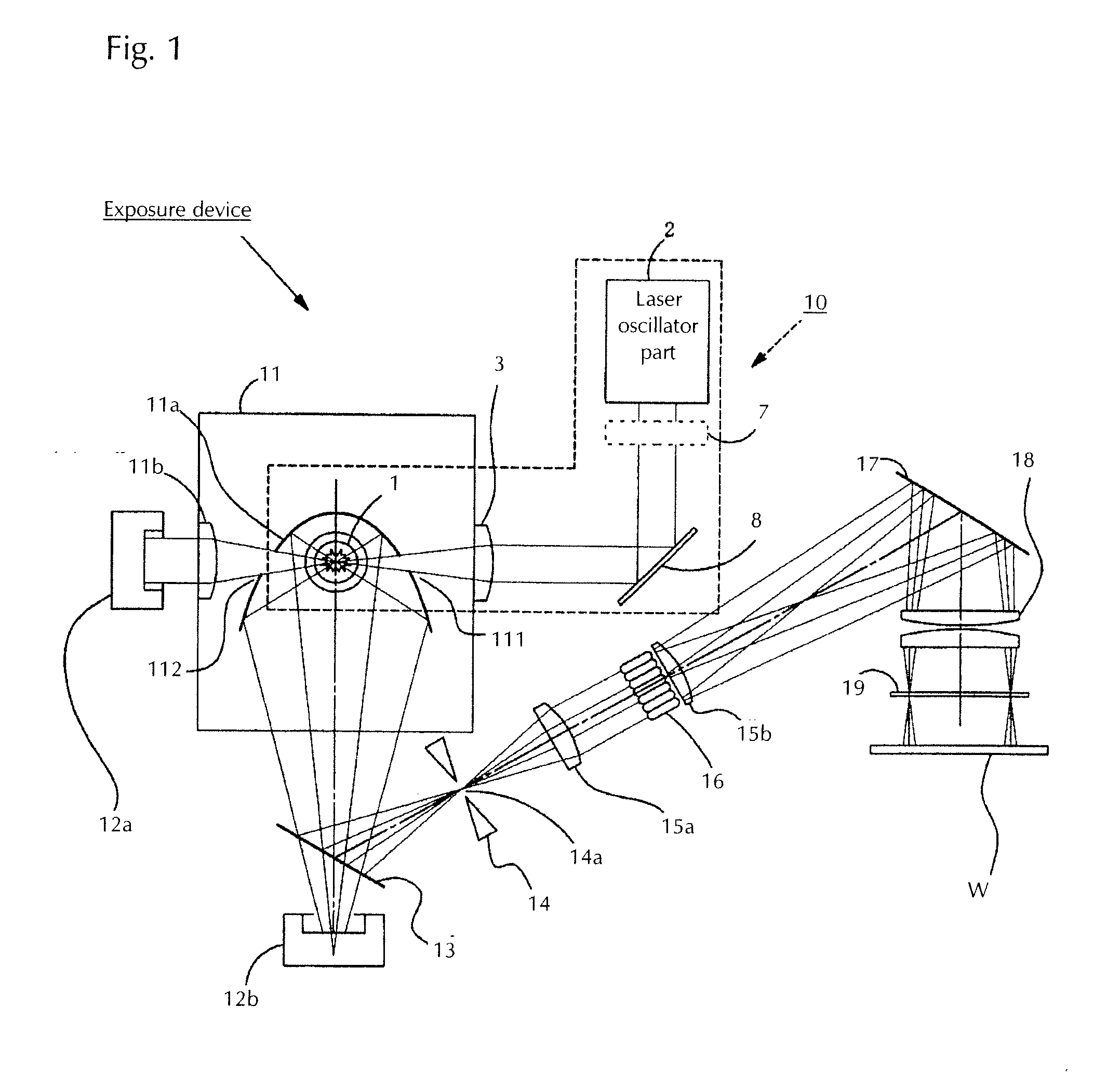
[0031]FIG. 1 is a view showing a configuration in which the light source device according to the present invention is used in an exposure device being one example for the use of the light source device. FIG. 2 is a view showing the light source device according to the present invention. First, the exposure device provided with the light source device of the present invention is explained by means of FIG. 1.

[0032]The exposure device is provided with a light source device 10 emitting light. As this light source device 10 is explained in detail using FIG. 2, it is only briefly explained here. The light source device 10 comprises a laser oscillator part 2, a focusing means 3 focusing the light from said laser oscillator part 2, and a light emission tube 1 irradiated with the light focused by said focusing means 3. In FIG. 1 only one laser oscillator part 2 is shown, but as mentioned below this laser oscillator part 2 consists of a pulsed laser oscillator part outputting a pulsed laser b...

second embodiment

[0063]Next, using FIG. 5, the present invention will be explained. The light source device shown in FIG. 5 uses a convex lens instead of the DOE 31 shown in FIG. 2 and consists of a light emission tube 1 in the interior of which a light emitting gas is enclosed and a convex lens 32 which is arranged such that the pulsed beam and the continuous-wave beam are focused in the interior of the light emission tube 1. In FIG. 5, the beams shown as ‘CW or pulsed’ and ‘pulsed or CW’ mean either one of a continuous-wave laser beam and a pulsed laser beam, and if one beam is a continuous-wave laser beam, the other one is a pulsed laser beam (the same applies to the embodiments below). For the optical means focusing in the interior of the light emission tube also a convex lens 32 as mentioned above can be used, and in this case each beam enters the convex lens 32 with the same angle.

[0064]Similar to the light source device of the first embodiment, also in the present embodiment the high-temperat...

third embodiment

[0065]Using FIG. 6, the present invention will be explained. In the device shown in FIG. 6, instead of the DOE 31 or the convex lens 32 shown in FIG. 2 and in FIG. 5 respectively a parabolic mirror 33 is arranged at a position surrounding the light emission tube 1, which mirror focuses in the interior of the light emission tube 1. In this case, the light path (optical axis) of the pulsed beam from the pulsed laser oscillator part and the light path (optical axis) of the continuous-wave beam from the continuous-wave laser oscillator part are arranged in parallel and are radiated to the reflecting surface of the parabolic mirror 33. At this time, the beams reflected by the reflecting surface are focused such that they are focused towards the interior of the light emission tube. Similar to the light source devices of the above mentioned embodiments, also in the present embodiment the high-temperature plasma state can be maintained stably, and as the continuous-wave beam has a smaller i...


PUM


Abstract

A light source device wherein the high-temperature plasma state after the start of the lighting is maintained stably and the light emission can be maintained stably and a decrease of the lighting life cycle by means of a heating of the light emission tube is suppressed comprises a light emission tube, in which a light emitting means is enclosed, and a pulsed laser oscillator part emitting a pulsed laser beam towards said light emission tube, wherein a continuous-wave laser oscillator part is provided emitting a continuous-wave laser beam towards said light emission tube.

Description

BACKGROUND OF THE INVENTION[0001]1. Field of Invention[0002]The present invention relates to a light source device lighted by means of a laser beam emitted from a laser device, which is ideally suited for use in an exposure device.[0003]2. Description of Related Art[0004]Light source devices which are configured such that a laser beam from a laser device is radiated towards a light emission tube in which a light emitting gas is enclosed, the gas is excited and light is emitted are known (see JP-A-61-193358 (1986)). With the device disclosed in JP-A-61-193358 (1986), a beam from a laser oscillator oscillating continuous or pulsed laser light is focused by a focusing component of an optical system such as a lens and radiated towards a light emission tube in which a light emitting gas (light emitting means) is enclosed. The light emitting gas in the light emission tube is excited and light is emitted. In lines 16 to 18 from the top of the right upper column on page 2 of JP-A-61-193358 ...

Claims


Application Information

Patent Timeline
Patent Type & Authority Applications(United States)
IPC IPC(8): H01S3/098
CPCH01J65/042G03F7/70008
Inventor YOKOTA, TOSHIO
Owner ENERGETIQ TECH
Learn More