Novel turbine and blades

a turbine blade and blade technology, applied in the field of turbines, can solve the problems of harmonic vibration and self-destruction, difficulty in speed regulation, etc., and achieve the effects of improving aerodynamic efficiency, low cut-in speed, and improving electrical power generation

Inactive Publication Date: 2011-02-03
WARNER DAVID B
View PDF23 Cites 52 Cited by
  • Summary
  • Abstract
  • Description
  • Claims
  • Application Information

AI Technical Summary

Benefits of technology

[0007]Briefly, the present invention is directed to a turbine. The turbine enhances electrical power generation across a range of very low to high fluid speed based on the synergistic effects of several design features. The turbine may include one or more of the following features: (1) multiple nested rotors each with its own blade set, with each rotor being arranged to independently rotate with a synergistic result; (2) an extremely low cut-in speed; (3) self-limiting functionality in fast fluid conditions; (4) a variable axis design that permits omni-directional energy harvesting; (5) soft, quiet blades; and / or (6) a self-balancing base.
[0008]Each rotor may include several blades and multiple hubs in a single assembly. At least one hub may operate an electrical generator. The shape and composition of the blades themselves may provide for “smart blades” that bend, stress, or otherwise re-shape themselves during operation to improve aerodynamic efficiency. Each blade may have a variable hardness, and a non-uniform, concavo-convex cross-sectional area that is a function of blade height.

Problems solved by technology

However, Darrieus-type designs may have inherent deficiencies, including (1) that only the middle one-third of the blade may efficiently create power; (2) that the farther the distance from a curved blade to its axis of rotation, the greater the likelihood of harmonic vibration and self-destruction; (3) needing assistance in starting; (4) using more energy than actually producing in some wind conditions; (5) exhibiting torque fluctuations during each revolution as the blades move into and out of the wind; and (6) difficulties with speed regulation in high wind speeds.

Method used


Image

  • Novel turbine and blades
  • Novel turbine and blades
  • Novel turbine and blades

Examples


Embodiment Construction

[0041]The following definition should be understood throughout this description and appended claims. A “fluid” refers to either gas or liquid, for example, air or water.

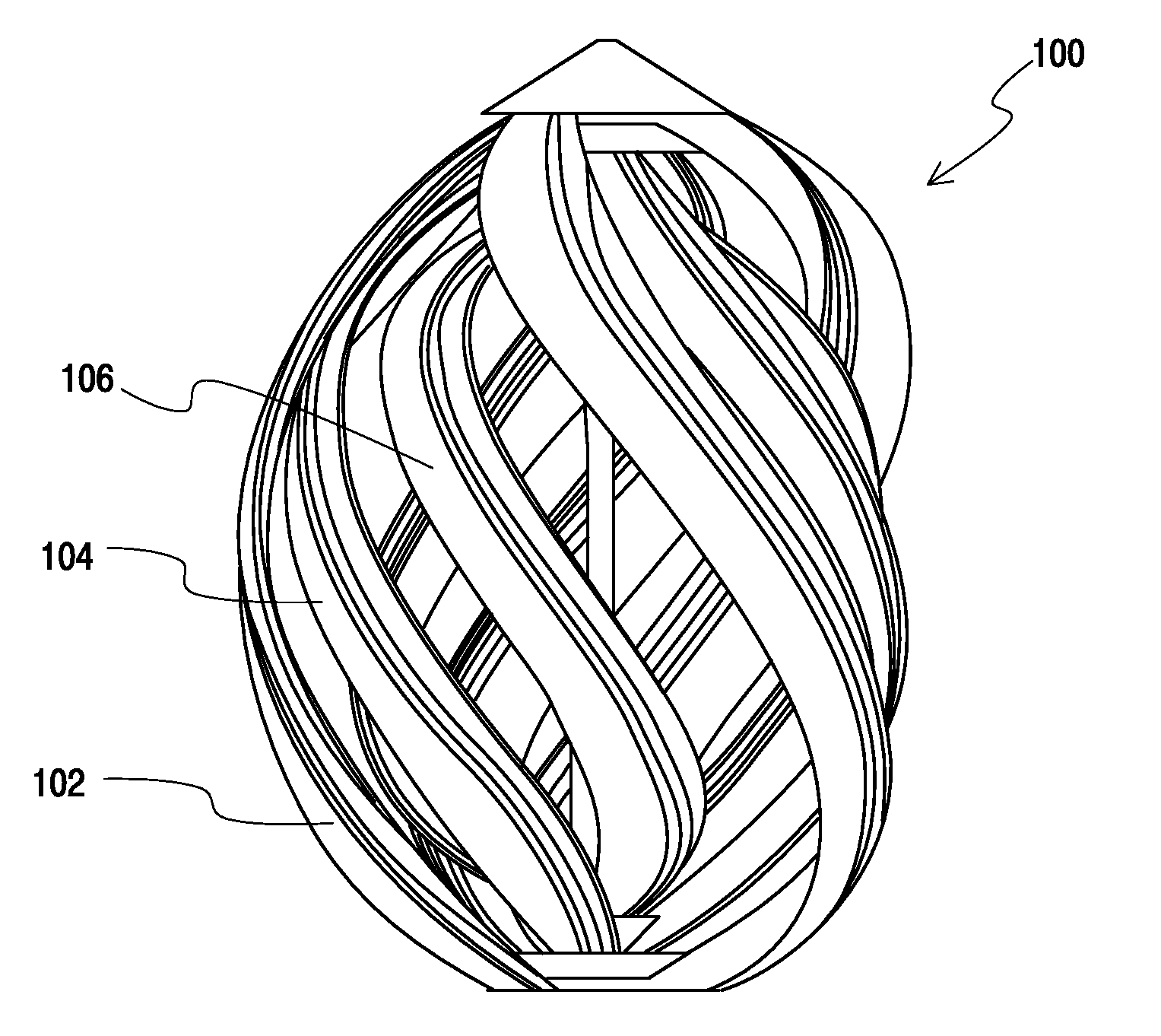
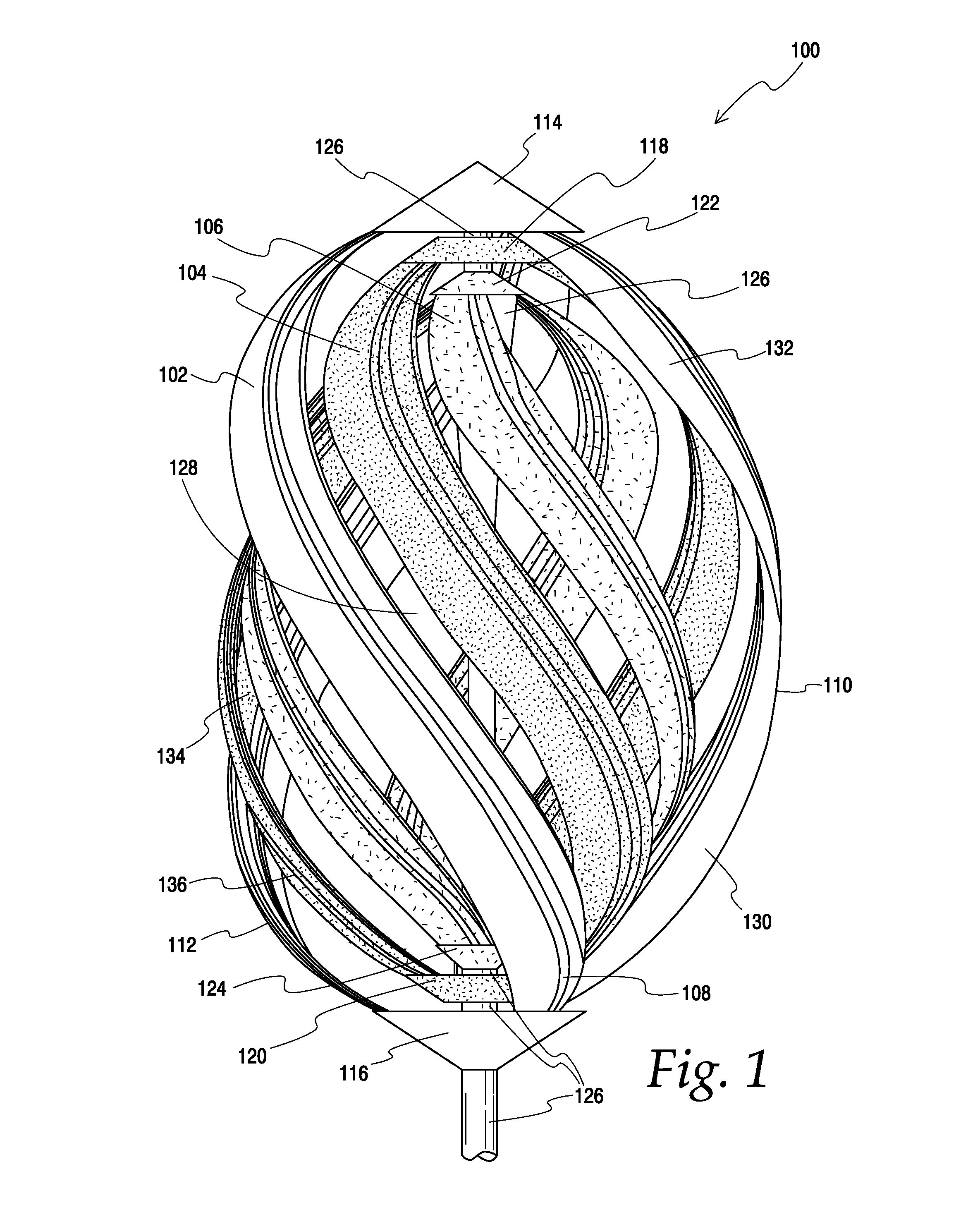
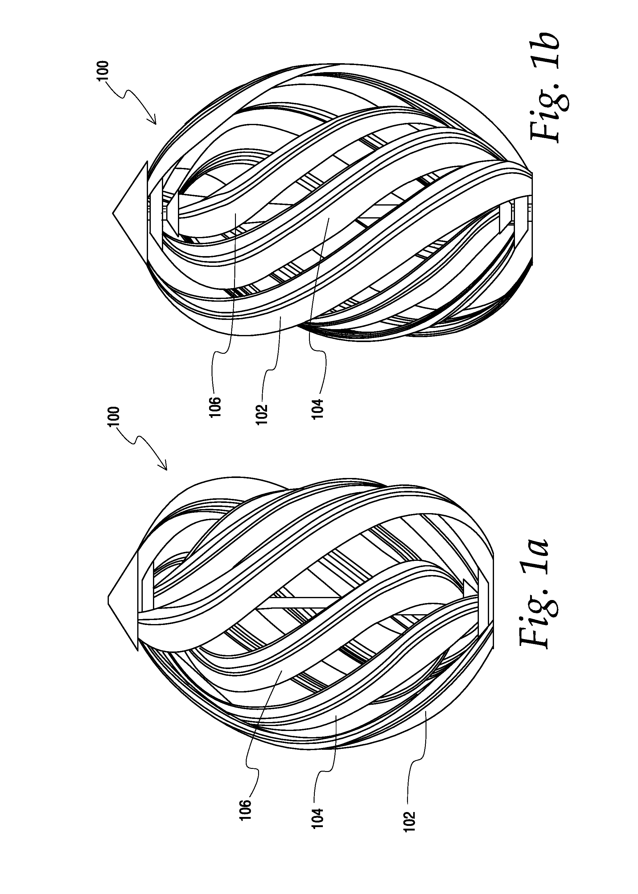
[0042]The embodiments described herein include apparatuses, systems, and methods for electric power generation and turbine manufacture. A variable axis turbine is provided that may generate electric power from wind or water. The turbine may include the nesting of multiple rotors, each with its own blade set. Each rotor and blade set may be configured to separately rotate around the same axis of rotation as the other rotors and blade sets. The nesting of multiple rotor blade sets may produce overall rotational energy in excess of the sum of the energy obtainable from the same blade sets operating at distances spaced from each other.

[0043]The turbine may be self-starting at very low fluid speed. Each blade may have a two-dimensional twist forming a concavo-convex cross-sectional area. As such, each blade may be shaped ...


PUM


Abstract

A variable axis turbine may include multiple nested rotatable rotor assemblies. The turbine may be self-starting in slow fluid conditions while simultaneously self-limiting in fast fluid conditions. The turbine may provide omni-directional energy recovery and be self-balancing. The nested rotatable rotor assemblies may be configured to rotate independently of each other, but along the same rotational axis. Each outer nested rotor blade set may direct fluid onto the inner rotor blade sets in an aerodynamically beneficial manner. Each rotor blade set may be interconnected with a rotating generator hub that encloses a rotating generator element that rotates along with a corresponding rotor blade set for electric power generation. The blades may be “smart blades” that are sufficiently flexible to be self-configuring during rotation and soft enough to partially absorb sound. The blades may have a variable hardness and a two or more dimensional twist.

Description

RELATED APPLICATIONS[0001]The present application claims the benefit of the filing date under 35 U.S.C. §119 (e) of U.S. Provisional Application Ser. No. 61 / 230,425, filed on Jul. 31, 2009 and entitled Variable Axis Turbine With Nested Rotor Blade Sets.BACKGROUND[0002]The present embodiments relate generally to turbines. More particularly, the present embodiments relate to turbines with multiple blade sets.[0003]Conventional wind turbines include the Darrieus design. A Darrieus-type configuration may include two curved blades whose ends are attached to fixed upper and lower hubs. Darrieus-type designs are disclosed in U.S. Pat. Nos. 1,835,018; 2,020,900; 4,112,311; 4,204,805 and 4,334,823. However, Darrieus-type designs may have inherent deficiencies, including (1) that only the middle one-third of the blade may efficiently create power; (2) that the farther the distance from a curved blade to its axis of rotation, the greater the likelihood of harmonic vibration and self-destructio...

Claims


Application Information

Patent Timeline
Patent Type & Authority Applications(United States)
IPC IPC(8): F03D3/02F03D3/06F03D11/04F03D11/02
CPCF03D3/02F03D3/061F05B2210/16F05B2240/301F05B2250/311Y02E10/74F05B2240/32F03D9/25
Inventor REKRET, ANDREW
Owner WARNER DAVID B
Why Eureka
Try Eureka