
Power tool

a technology of power tools and lubricants, applied in the field of power tools, can solve problems such as lubricant may possibly leak from the housing to the outside, and achieve the effect of effectively preventing lubricant leakag

Active Publication Date: 2011-02-10
MAKITA CORP
View PDF7 Cites 14 Cited by
  • Summary
  • Abstract
  • Description
  • Claims
  • Application Information

AI Technical Summary

Benefits of technology

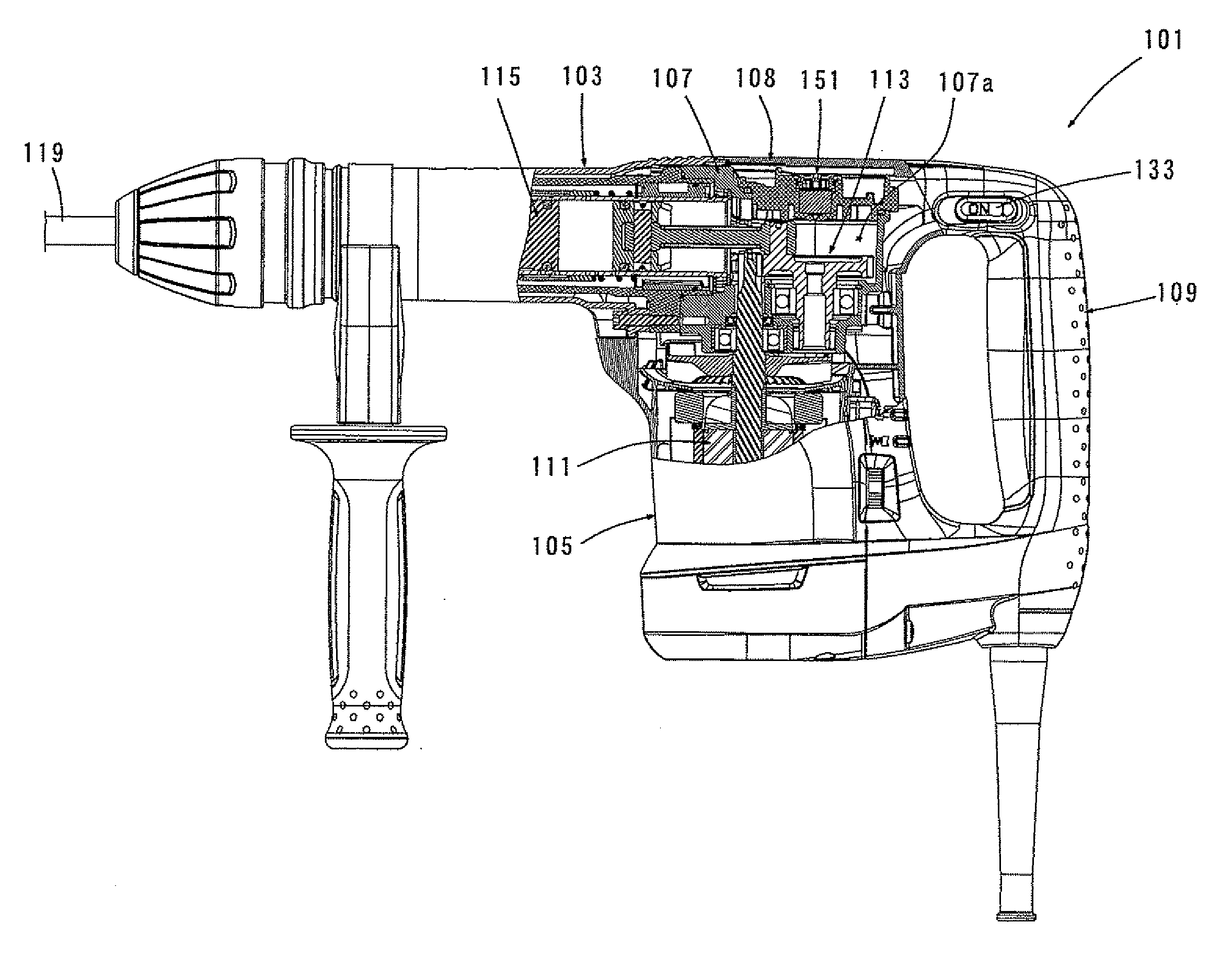
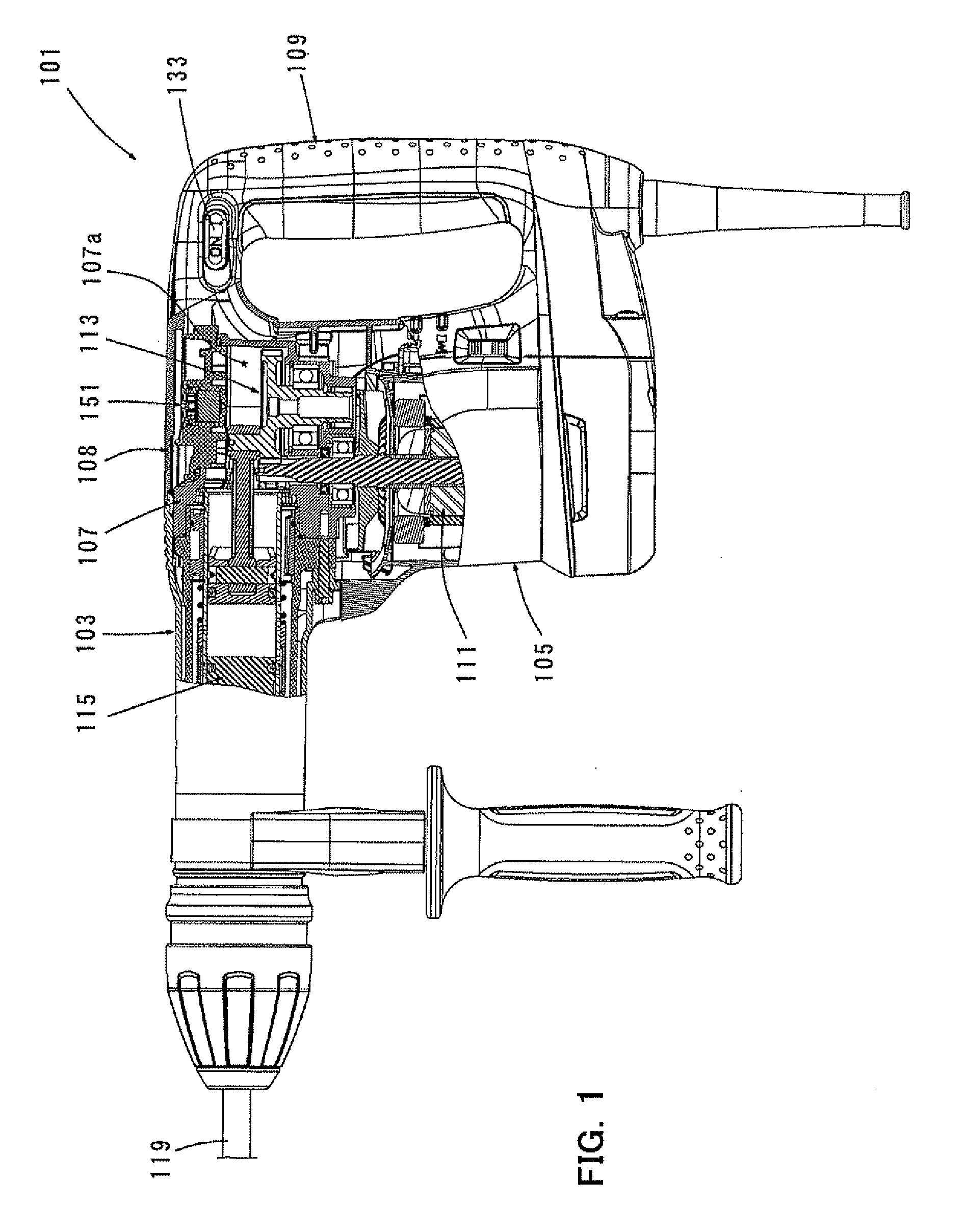
Accordingly, it is an object of the invention to provide a power tool that effectively prevents leakage of lubricant while regulating the internal pressure of a housing space for a driving mechanism.
With such a construction, when the internal pressure of the housing space abnormally increases during an operation of the power tool, air within the housing space flows out through the path, so that the internal pressure of the housing space is regulated. Specifically, pressure of the housing space is released. Therefore, if the power tool is an impact power tool such as an electric hammer or hammer drill, striking failure of the driving mechanism which may be caused by pressure increase within the housing space can be prevented.
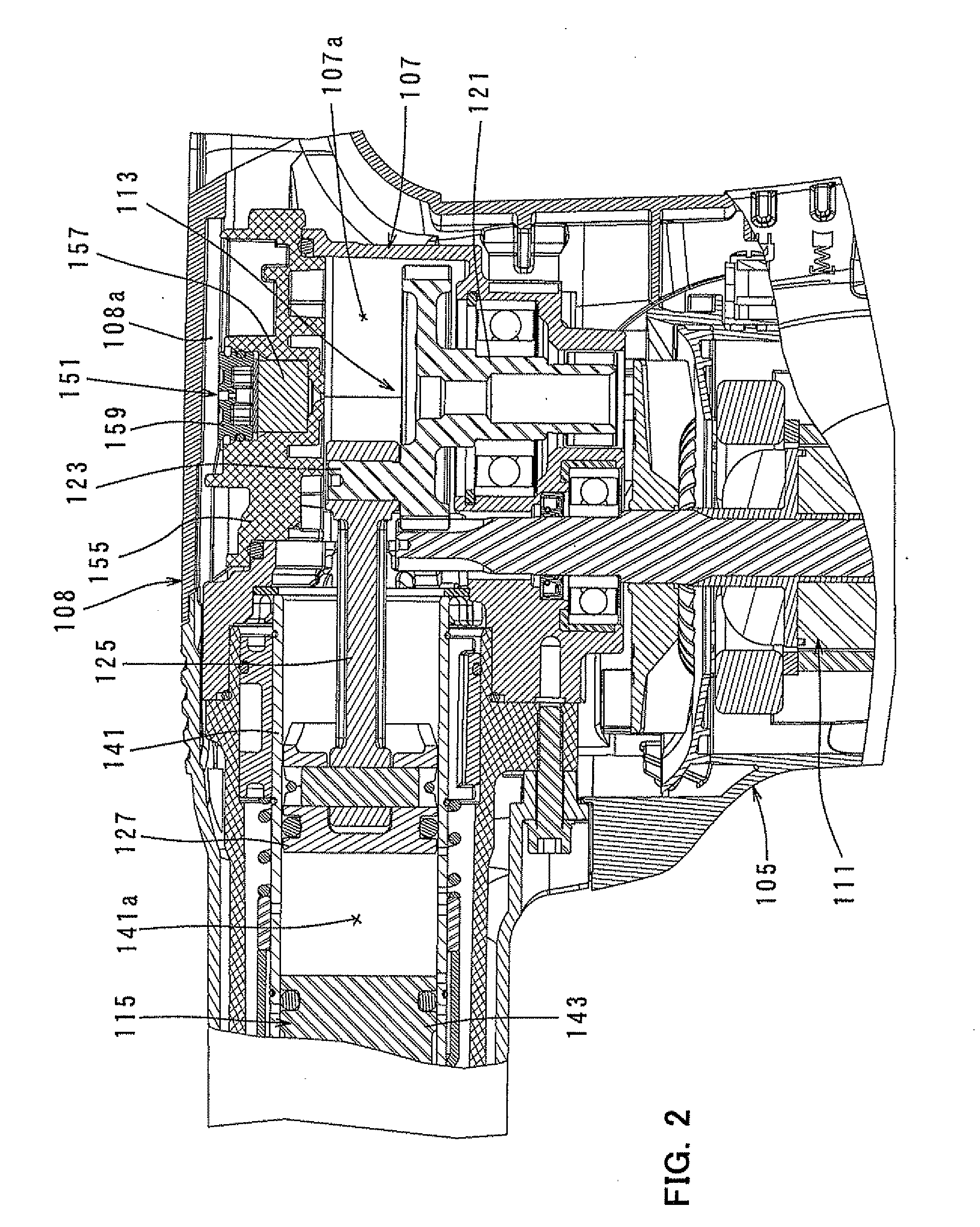
According to the invention, when lubricant within the housing space flows out through the path together with air, the lubricant can be caught by the filter, so that the outflow of the lubricant to the outside can be prevented. On the other hand, depending on the velocity of flow of air which passes through the filter, some of the lubricant may possibly pass through the filter without being absorbed by the filter. Therefore, in this invention, in order to reduce the velocity of flow of air which flows through the filter, a space is formed on the outer passage side of the filter chamber, and a throttle member for throttling flow of air which flows out to the outer passage through the filter is disposed in the space. Specifically, in this invention, a member for reducing the outflow of the air is provided on the downstream side of the filter with respect to the air flow from the housing space to the outside. Thus, the lubricant absorbing effect of the filter can be enhanced, so that the outflow of the lubricant to the outer passage can be prevented. According to this invention, lubricant can be effectively prevented from leaking from the housing space to the outside while the internal pressure of the housing space is regulated.
Further, as another aspect of the invention, when the sheet member is used as the throttle member, the sheet member may be formed of circular elastic material, Further, a throttle passage may be defined by an outer circumferential surface of the elastic material and a peripheral wall surrounding the outer circumferential surface and communicates the filter with the space. Generally, air flows through the filter straight ahead toward the outer passage. According to this invention, however, by providing the throttle passage radially outside the elastic material, the elastic material serves as a blocking member for blocking flow of air which flows through the filter straight ahead toward the outer passage. Therefore, air which is prevented from flowing straight ahead by the elastic material flows radially outward from the central portion of the filter to the throttle passage. Thus, the distance of air flow through the filter can be elongated. As a result, a catch region (contact region) of the filter which catches or contacts the lubricant is enlarged, so that the filter can be effectively utilized in its entirety as a region of absorbing the lubricant.
Further, as another aspect of the invention, the throttle member may preferably include a second filter which is disposed in the space in such a manner as to be held in contact with the opening edge of the outer passage open to the filter chamber and spaced apart from the filter. As the “second filter” according to this invention, typically, felt, sponge or cloth may be suitably used, but any other material which can absorb and catch the lubricant can also be used. According to this invention, the second filter serves as a member for throttling flow of air which flows out to the outer passage. As a result, the velocity of flow of air which flows through the filter can be reduced, so that the lubricant absorbing effect of the filter can be enhanced. Further, the second filter itself can catch the lubricant which is flowing out to the outer passage. Therefore, lubricant can be effectively prevented from leaking to the outside.
Further, as another aspect of the invention, the power tool may further include a dynamic vibration reducer having a weight elastically held. The dynamic vibration reducer reduces vibration caused in the power tool during the operation by means of a reciprocating movement of the weight. The dynamic vibration reducer utilizes the pressure which fluctuates in the housing space as a force of driving the weight and the throttle enhances hermeticity of the housing space.

Problems solved by technology

As a result, lubricant may possibly leak from the housing to the outside.

Method used


Image

  • Power tool
  • Power tool
  • Power tool

Examples


Embodiment Construction

Each of the additional features and method steps disclosed above and below may be utilized separately or in conjunction with other features and method steps to provide and manufacture improved power tools and method for using such power tools and devices utilized therein. Representative examples of the present invention, which examples utilized many of these additional features and method steps in conjunction, will now be described in detail with reference to the drawings. This detailed description is merely intended to teach a person skilled in the art further details for practicing preferred aspects of the present teachings and is not intended to limit the scope of the invention. Only the claims define the scope of the claimed invention. Therefore, combinations of features and steps disclosed within the following detailed description may not be necessary to practice the invention in the broadest sense, and are instead taught merely to particularly describe some representative exam...


PUM

PropertyMeasurementUnit
pressureaaaaaaaaaa
weightaaaaaaaaaa
internal pressureaaaaaaaaaa

Abstract

It is an object of the invention to provide a power tool that effectively prevents leakage of lubricant while regulating the internal pressure of a housing space for a driving mechanism.The object can be achieved by a representative power tool that includes a too bit 119, a driving mechanism 113, 115, an enclosed housing space 107a which houses the driving mechanism and in which lubricant is sealed in, and a path 151 which regulates pressure of the housing space 107a. On the path, a filter chamber 154 having a predetermined capacity, an inner passage 155c that communicates the filter chamber 154 with the housing space 107a, and an outer passage 159c that communicates the filter chamber 154 with the outside are formed. A filter 157 is disposed in the filter chamber 154 and spaced apart from a peripheral edge of an opening of the outer passage 159c which is open to the filter chamber 154, so that a space 161 is created on the opening edge side of the filter chamber 154. A throttle member 163, 167 is disposed in the space 161 and throttles flow of air which flows out to the outer passage 159c through the filter 157.

Description

BACKGROUND OF THE INVENTION1. Field of the InventionThe invention relates to a power tool and more particularly, to a power tool which can regulate internal pressure of a housing space for a driving mechanism.2. Description of the Related ArtAn electric hammer is known including a driving mechanism housed within a housing and driven by a motor to drive a tool bit for performing a striking movement in its axial direction and a rotation in its circumferential direction. Lubricant such as grease for lubricating the driving mechanism is provided within the housing space that houses the driving mechanism. The housing space is enclosed for preventing the charged lubricant from leaking to the outside. In such a construction, when the known hammer is operated, air within the housing is heated by an operation of the driving mechanism, such that the air within the housing expands to increase inside pressure. As a result, lubricant may possibly leak from the housing to the outside.In this resp...

Claims


Application Information

Patent Timeline
Patent Type & Authority Applications(United States)
IPC IPC(8): E21B12/00
CPCB25D17/245B25D17/26B25D2211/003F16H57/027B25D2250/185B25F5/006B25F5/02B25D2217/0084
Inventor KAKIUCHI, YASUHIROBITO, SHINYA
Owner MAKITA CORP
Learn More