Apparatus for Displaying, Monitoring and/or Controlling Shower, Bath or Sink Faucet Water Parameters with an Audio or Verbal Annunciations or Control Means

Active Publication Date: 2011-02-10
KLICPERA MICHAEL
View PDF9 Cites 90 Cited by
  • Summary
  • Abstract
  • Description
  • Claims
  • Application Information

AI Technical Summary

Benefits of technology

[0014]The present invention is a display apparatus that is in communication with a shower sink or bath water supply piping or incorporated within a shower, bath or sink faucet, in an aesthetically pleasing format and comprised of fabrication materials e.g., a polymeric or metallic bases with chrome, brass white or colored finishes or combination of these finishes and materials of construction. The display apparatus includes a power generation, a microprocessor, temperature and/or water flow sensors, timing circuits and a display means. The display means can be an analog or digital display or combination of display means and can have touch screen capability or ergonomically placed buttons can be incorporated into the display means to change parameter units (e.g. metric to US), set alarm conditions (e.g. temperature over set point, time past a set point, volume (gallons) that passed a set point). The display means must be able to provide sufficient lighting in shower conditions. In addition, the display means must be able to sustain capability in moist wet conditions. In some embodiments defined attachment to a shower display apparatus, know piping joint technology will be used for installation into both new and presently installed shower systems. In the embodiment defined by the display means incorporate into the shower head th

Problems solved by technology

The hole often leads to water seeping under the bath tub.
Furthermore, these drawbacks (difficulty of storage and problems with dirt) make it undesirable to install a longer hose, eve

Method used


Image

  • Apparatus for Displaying, Monitoring and/or Controlling Shower, Bath or Sink Faucet Water Parameters with an Audio or Verbal Annunciations or Control Means
  • Apparatus for Displaying, Monitoring and/or Controlling Shower, Bath or Sink Faucet Water Parameters with an Audio or Verbal Annunciations or Control Means
  • Apparatus for Displaying, Monitoring and/or Controlling Shower, Bath or Sink Faucet Water Parameters with an Audio or Verbal Annunciations or Control Means

Examples


first embodiment

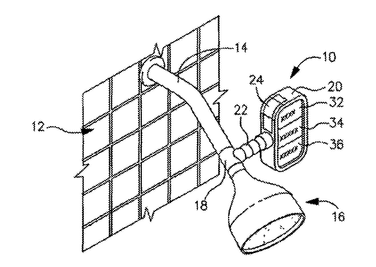
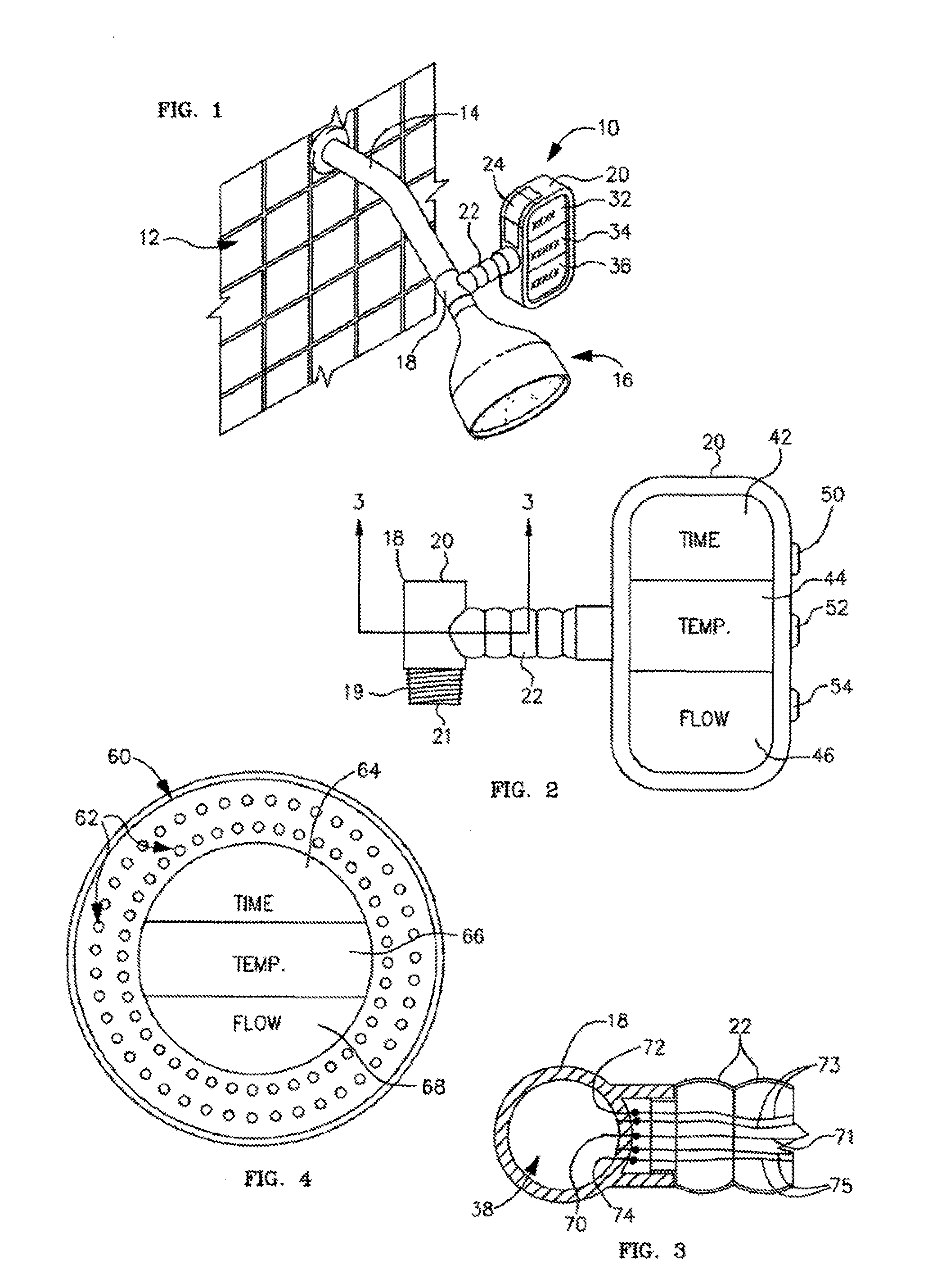
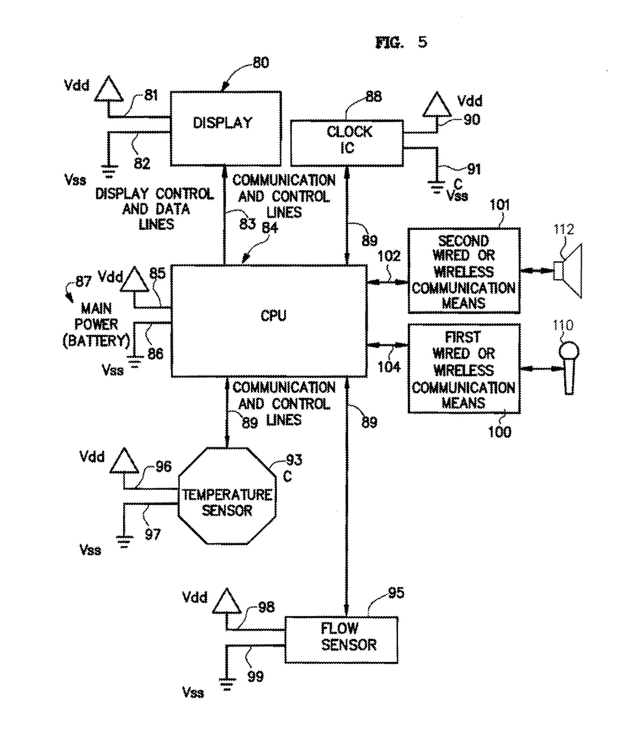
[0034]Now referring to FIG. 2, the present invention display apparatus 10 includes a housing 20, a computerized circuit board having a power source 87 (depicted in FIG. 5), the display means housing having a water tight door 24 for replacing or regenerating the power source (shown in FIG. 1) and an one or more buttons or activators that allow for certain modification of the software instructions (change units, input timing, alarms). The housing 20 can be fabricated from a metallic material such as brass, brass alloys, steel, galvanized steel, copper, copper allows or any combination thereof. The display means housing can be fabricated from a number of polymeric materials, such as polyvinyl chloride (PVC), polyethylene, polybutylene, acryaontirile-butadiene-styrene (ABS), rubber modified styrene, polypropylene, polyacetal, polyethylene, or nylon. The base material can be painted white or colored finishes or coated with various brass, silver and gold type materials to accommodate the ...

second embodiment

[0105]FIG. 4 is a perspective view of the second embodiment showing the display apparatus incorporated within the shower head in accordance with the present invention. It is anticipated by the Applicant that the technology of the present invention can also be incorporated within a faucet head (not shown).

[0106]The display (as presented in FIG. 4 in general means 64, 66, and 68 utilizes one or more illuminating technologies, such as LCD, LED, gas plasma, fluorescence, incandescent, halogen, halide, or other lighting technologies but must able to provide sufficient lighting for observing the data in shower conditions. In addition, the display means must be able to sustain capability in moist wet conditions. The present invention can include one or more than one display parameter. For example, a unit with only the temperature display can be manufactured to reduce overall costs. Furthermore, the orientation of the parameters 64, 66, and 68 presented can be changed, for example, the flow...

third embodiment

[0141]FIG. 8 is a perspective view of a third embodiment showing the display apparatus 130 extending from a typical sink 120, having a drain 124, overflow drain 126, drain control knob 128, single valve hot or cold control valve 127, and sink faucet 122. The display apparatus is shown displaying water parameters and having a speaker 110 and microphone 112. The electrical circuitry and microprocessor can be located with the display apparatus 130 or can be positioned in a remote location e.g. under the sink, and electronically communicate with the display apparatus 130, microphone 112 or speaker 110 using wired or wireless technology.

[0142]It is also anticipated that standard sink and bath faucets, and current faucets which have motion or infra-red sensors for turning on an off the water supply could benefit from the audio or verbal detection means described herein. The disadvantage of the current faucets with motion or infra-red sensors technology is that the individual user has no c...


PUM


Abstract

The present invention is a display apparatus for affixation to shower head, bath or sink faucet water supply piping or incorporated within a shower, or bath or faucet head. The display apparatus includes a power generation, CPU or microprocessor, temperature sensor and/or water flow sensors, timing circuits, and audio or verbal communication means and a display means. The present invention can position some components remotely from other components that communicate by wired or wireless means. The communication means is designed 1) to detect and respond to audio signals or verbal instructions or commands and/or 2) annunciate audio signals or verbal messages.

Description

RELATED APPLICATIONS[0001]This application is a continuation-in-part of U.S. patent application Ser. No. 11 / 877,860 filed on Oct. 24, 2007 and U.S. patent application Ser. No. 12 / 539,150 filed on Aug. 11, 2009 and Provisional Application Ser. No. 61 / 241,111 filed on Sep. 10, 2009.FIELD OF THE INVENTION[0002]This apparatus and the method of use relates to shower or bath heads and water supply piping, more particularly, to shower head, faucet, bath or water supply piping having a visual analog or digital display of certain parameters of the supplied water, such as the temperature, flow rate, and time and timing parameters.BACKGROUND OF THE INVENTION[0003]Conventional shower head designs include those having a shower head housing with a plurality of passageways allowing various water sprays to flow from the shower head. Furthermore, shower heads having a surface with a plurality of passageways, or nozzle orifices which utilize a backing disk having a plurality of resilient and flexible...

Claims


Application Information

Patent Timeline
IPC IPC(8): B67D7/08
CPCB05B1/18G10L2015/223B05B12/008B05B12/02B05B12/12E03B7/04E03C1/0408E03C2001/0418G01F15/024G01F15/063G01F15/075G01F15/0755G01K13/02G01K2013/026G01K2207/00G10L15/22B05B12/004Y10T137/8158Y02A20/00G01K13/026
Inventor KLICPERA, MICHAEL
Owner KLICPERA MICHAEL
Why Eureka
Try Eureka