Light emitting diode (LED) driving circuit

a technology of led driving circuit and led diodes, which is applied in the direction of electric variable regulation, process and machine control, instruments, etc., can solve the problems of deteriorating the light quality of the resulting white light, different conductance of the backlight module, and the lcd or plasma display panel itself not producing light, so as to improve the white light quality and reduce power consumption.

Active Publication Date: 2011-02-10
CHUNGHWA PICTURE TUBES LTD
View PDF8 Cites 9 Cited by
  • Summary
  • Abstract
  • Description
  • Claims
  • Application Information

AI Technical Summary

Benefits of technology

[0007]Accordingly, the present invention is directed to provide an LED driving circuit that adjusts the voltage level of a driving voltage according to the variation in electrical characteristics among the driven LEDs or LED strings. The LED driving circuit can drive LEDs with different conducting voltage levels, achieve better white light quality, and reduce power consumption.

Problems solved by technology

However, the LCD or plasma display panels themselves do not generate light.
However, the inevitable variation in raw material and manufacturing process will cause the LED strings in a backlight module to have different conducting (i.e. turning-on) voltages.
The incoherent light luminance of the three lights will deteriorate the light quality of the resulting white light.
However, the solution will waste more power and curtail the life of the overdriven LEDs.

Method used


Image

  • Light emitting diode (LED) driving circuit
  • Light emitting diode (LED) driving circuit
  • Light emitting diode (LED) driving circuit

Examples


Embodiment Construction

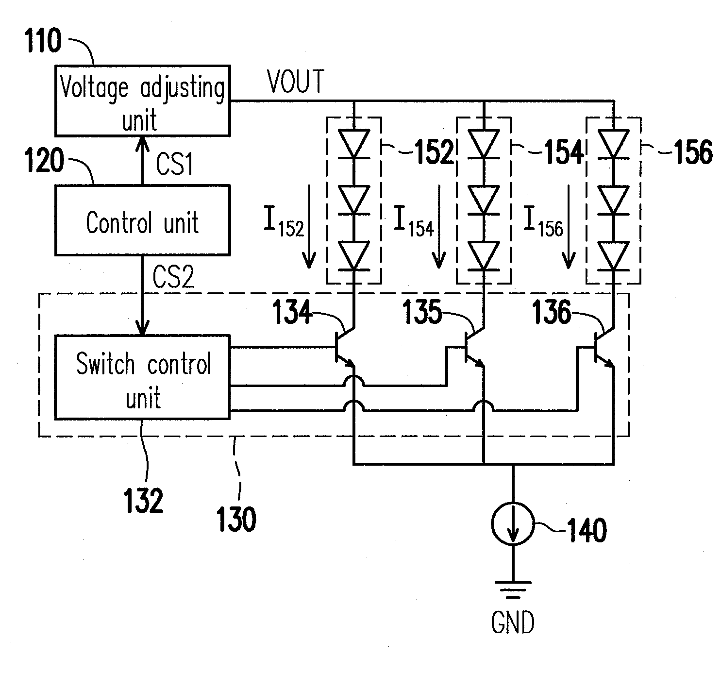
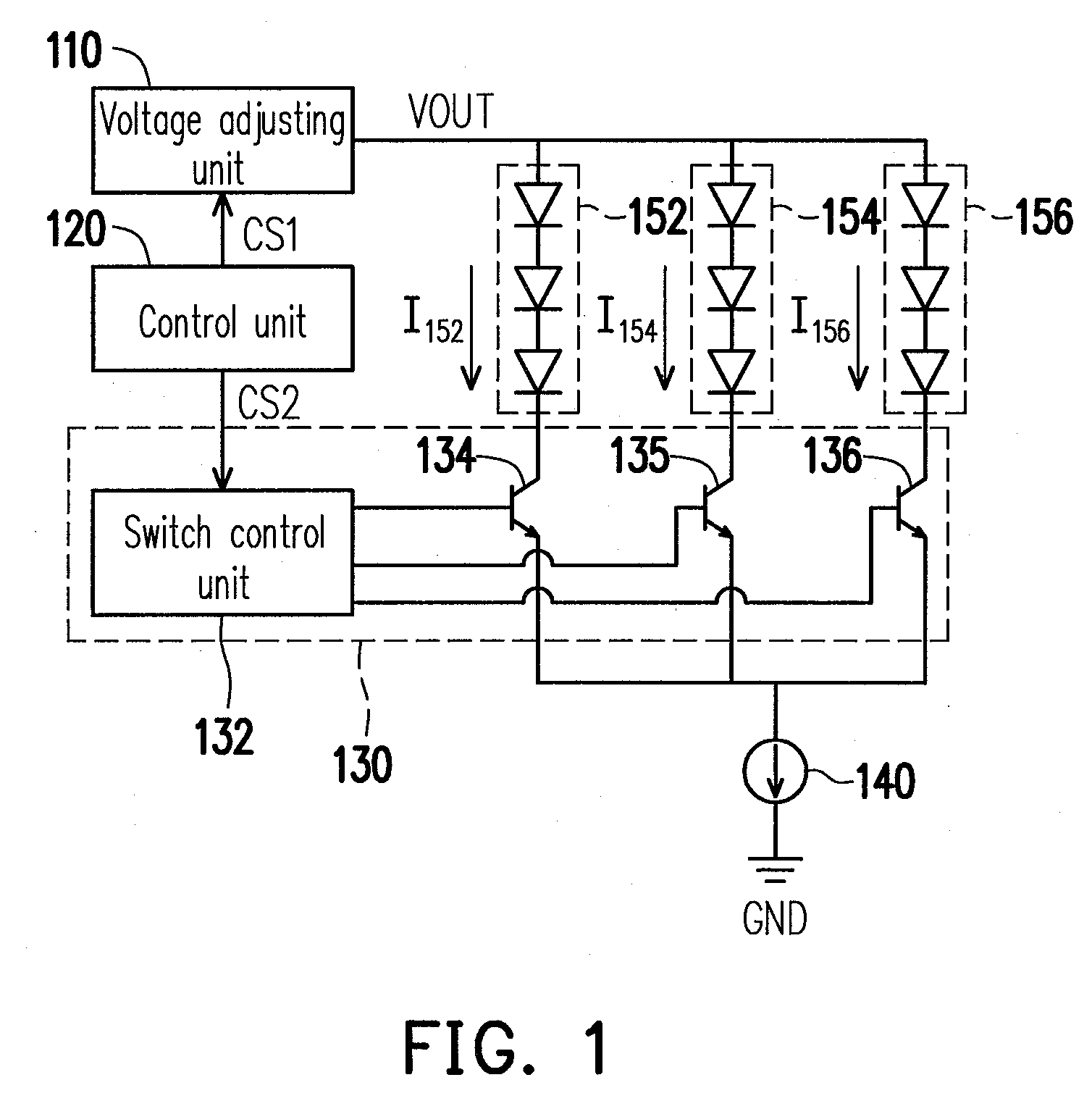
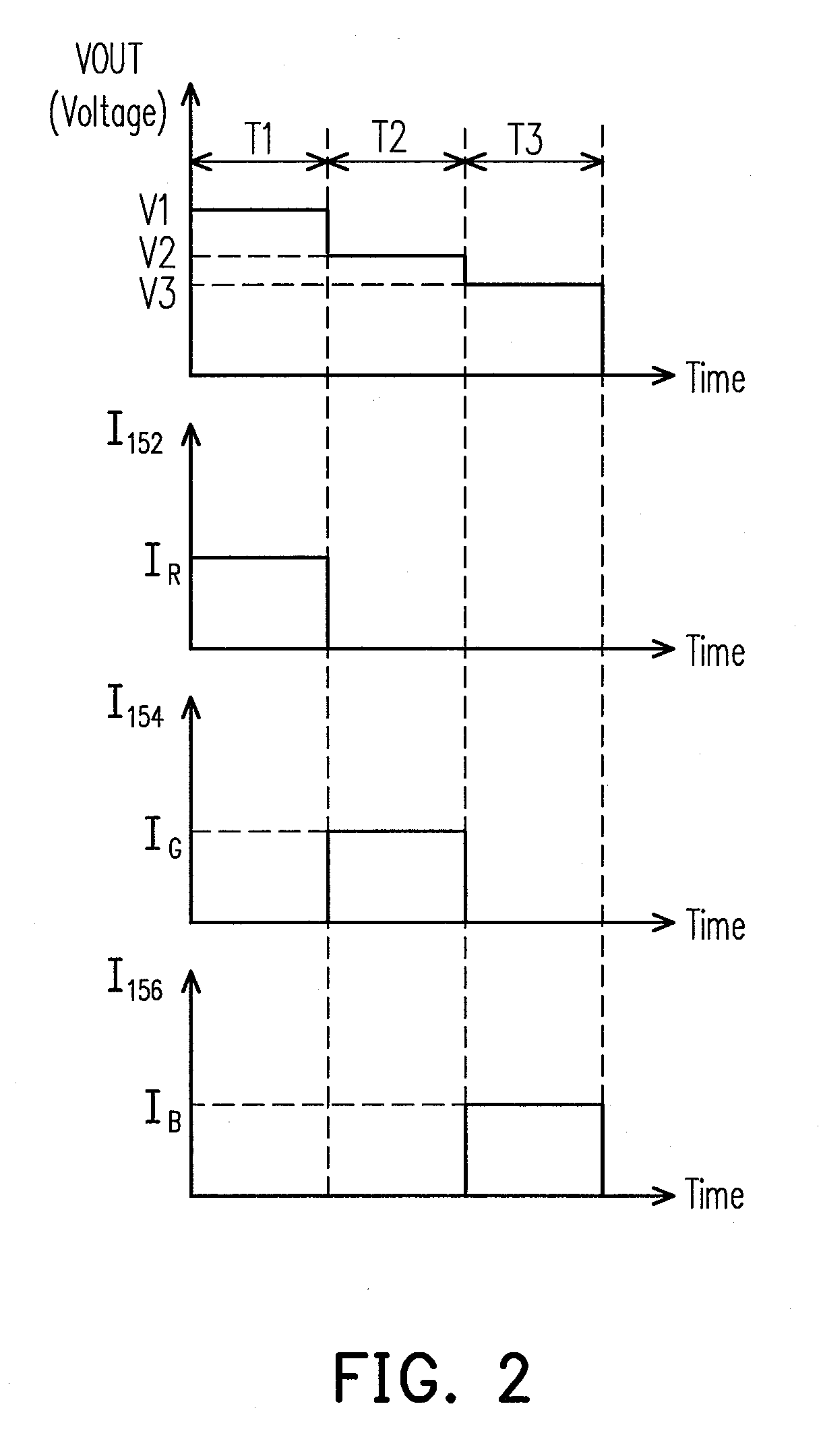
[0023]FIG. 1 is a circuit diagram of a driving circuit according to an embodiment of the present invention. FIG. 1 shows not only the driving circuit but also load units 152, 154, and 156. The driving circuit includes a voltage adjusting unit 110, a control unit 120, a switch unit 130, and a current source 140. The switch unit 130 includes a switch control unit 132 and switches 134, 135, and 136. The switches 134, 135, and 136 can be embodied by transistors, such as NPN or PNP bipolar junction transistors (BJTs), or N channel metal oxide semiconductor transistors (NMOSs), or P channel metal oxide semiconductor transistors (PMOSs). The load units 152, 154, and 156 can be LED strings in a backlight module.

[0024]The control unit 120 is coupled to the voltage adjusting unit 110 and the switch control unit 132. The control unit 120 outputs a first control signal CS1 to the voltage adjusting unit 110 and outputs a second control signal CS2 to the switch control unit 132. The voltage adjus...


PUM

PropertyMeasurementUnit
driving voltageaaaaaaaaaa
voltageaaaaaaaaaa
constant currentaaaaaaaaaa

Abstract

A light emitting diode (LED) driving circuit is provided. The LED driving circuit includes a voltage adjusting unit, a switch unit, and a control unit. The control unit is coupled to the voltage adjusting unit and the switch unit. The voltage adjusting unit outputs a driving voltage to a first end of each of a plurality of load units. The switch unit is coupled to a second end of each of the load units. When one LED string in the load units is coupled to a current source, the voltage adjusting unit adjusts the voltage level of the driving voltage so that the voltage level of the driving voltage of the driving voltage corresponds to the driven LED string. Thereby, a driving problem caused by the variation in electrical characteristics of the LEDs is alleviated.

Description

CROSS-REFERENCE TO RELATED APPLICATION[0001]This application claims the priority benefit of Taiwan application serial No. 98126383, filed on Aug. 5, 2009. The entirety of the above-mentioned patent application is hereby incorporated by reference herein and made a part of this specification.BACKGROUND OF THE INVENTION[0002]1. Field of Invention[0003]The present invention relates to Light Emitting Diode (LED) driving circuits. More particularly, the present invention relates to LED backlight driving circuits.[0004]2. Description of Related Art[0005]Electronic devices, such as mobile phones, laptop computers, and personal digital assistants (PDAs), frequently use liquid crystal displays (LCDs) or plasma displays as monitors. However, the LCD or plasma display panels themselves do not generate light. There should be a backlight module mounted to the back of an LCD or plasma panel to provide the light required by the panel. Currently used backlight modules include flat fluorescent lamps ...

Claims


Application Information

Patent Timeline
Patent Type & Authority Applications(United States)
IPC IPC(8): H05B41/36
CPCH05B33/0818Y02B20/347H05B33/0824H05B45/375H05B45/38H05B45/44Y02B20/30
Inventor LIU, CHIA-LINLI, LINGPENG, CHIA-LINGLO, KUO-CHUNGMO, CHI-NENG
Owner CHUNGHWA PICTURE TUBES LTD
Why Eureka
Try Eureka