3D autostereoscopic display with true depth perception

Inactive Publication Date: 2011-02-10
LIGHT PRESCRIPTIONS INNOVATORS
View PDF16 Cites 43 Cited by
  • Summary
  • Abstract
  • Description
  • Claims
  • Application Information

AI Technical Summary

Benefits of technology

[0007]An embodiment of the presently proposed autostereoscopic display will have two scene projectors. The exit pupil of one projector is conjugated with the pupil of the left eye of the observer, while the exit pupil of the second projector is conjugated with the pupil of the right eye of the observer. The projector pupil diameter exceeds the eye pupil

Problems solved by technology

This creates unnatural perception of a 3D scene that contains a number of objects at different supposed distances, for example, scenes with a close object in front of a landscape background.
The problem is that the number of distance “slices” is in practice restricted to 2, and such an arrangement has problems with simulation of combinations of cl

Method used


Image

  • 3D autostereoscopic display with true depth perception
  • 3D autostereoscopic display with true depth perception
  • 3D autostereoscopic display with true depth perception

Examples


second embodiment

[0039]The optical prescription of a suitable projector with extended field of view and larger eye box is shown in Table 3.

TABLE 3Distance toGlass to nextApertureSurfaceRadiusnext surfacesurface(mm)ObjectInfinity10.41Air7.41Infinity−6Mirror-air2−629.07−0.5F2325.26−1BK74−37.57−2.33Air5Five values2.33Mirror-air106−37.571BK7725.260.5F28−629.076Air9Infinity9.29Air10−552.0810.51LAK911−50.130.15Air12209.734.85LAK1813−132.763.35Air14−46.315.45SF1115205.255.81Air16Infinity2.64Air17−47351.602SF1018−23.4510.41LASF4319−51.776.5Air20−32.694.306BK7214933.905Air22−274.845.45LASF4123−53.82100Air24Aperture Infinity0Air2Stop(Eye)25Eye lensParaxial F = 171726Image Plane 01.7(Retina)

first embodiment

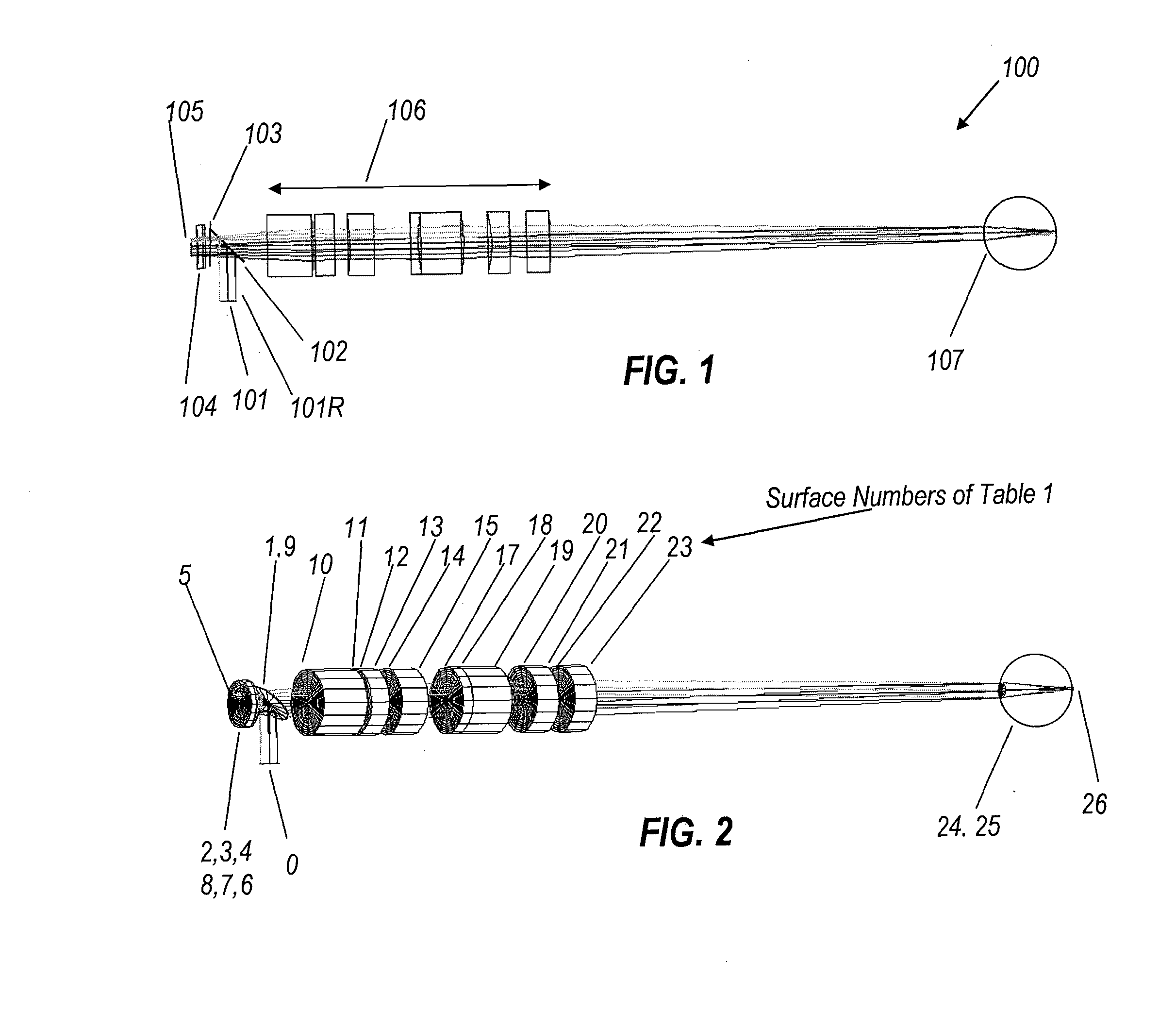
[0040]The image source of projector 700 shown in FIG. 7, (“object” in the example in Table 3) is the same compact transmission liquid crystal display 701 as in the Beamsplitter 702 (Surface 1 in Table 3), directs the display output to the assembly of negative achromatic doublet 703 (bounded by surfaces 2, 3, and 4) and micromachined membrane mirror 704 (surface 5) made by Flexible Optics Corp or equivalent component from another manufacturer. After reflection at the membrane mirror, a 2D image “slice” passes back through achromatic doublet 703 (surfaces 6, 7, and 8) and beamsplitter 702 (inactive surface 9) and is projected to the eye by reverse telephoto lens 705 (surfaces 10 through 23). Optically inactive surface 16 is an aperture stop of the reverse telephoto lens, and is separately enumerated for convenience. The position of the exit pupil of the projection lens is conjugated with the eye pupil of the observer. The diameter of the exit pupil of the projection lens exceeds the ...

embodiment 1000

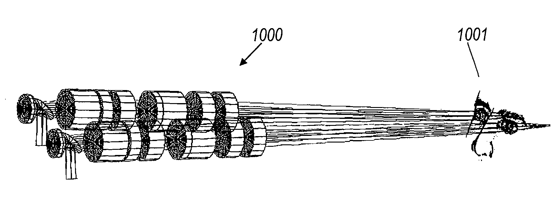
[0051]Referring to FIG. 10, a preferred embodiment 1000 of the binocular projection system is disclosed herein comprising two projectors, each of which may be as shown in FIGS. 1 and 2 or in FIG. 7, serving observer 1001. Each projector dynamically creates a succession of depth-slices of a 3D scene, wherein each stereo pair of depth slices has a disparity and apparent image distance that are in accordance with the supposed distance from the objects depicted in that slice to the observer.

[0052]The displays 101, 701 and the mirrors 105, 705 or other optical elements of variable power are controlled by a driver, shown functionally in FIG. 11. The driver typically comprises a processor, non-volatile memory or other storage media for programs, volatile working memory, and storage and / or input for video data. The driver is arranged in use to cause the display to generate successive outputs representing slices of a scene at different distances from an observer position, and to cause the op...


PUM


Abstract

An autostereoscopic display provides true natural perception of 3D scenes by projecting depth-slice images of objects located at different distances, so during each video frame the scene is segmented into five or more different depths and then each displayed in succession with both the stereo disparity and apparent image distance proper for each depth.

Description

CROSS REFERENCE TO RELATED APPLICATIONS[0001]This application claims benefit of U.S. Provisional Patent Application No. 61 / 273,743, filed Aug. 7, 2009, which is incorporated herein by reference in its entirety.BACKGROUND OF THE INVENTION[0002]The perception of 3D scenes by human vision is largely based on two mutually interacting visual adaptation processes—stereoscopy and the eye's focal accommodation to object distance. Because the typical eye separation is about 60 mm, fixation upon objects at different distances gives different angles of convergence between the axes of the eyes, known as the “stereovision” effect or “stereoshift.” Though usually unconscious, this convergence angle is registered by the brain and contributes to the perception of object distance. To provide high resolution imaging of objects at different distances, the eye adjusts the shape, and thus the optical power, of the lens so it sharply focuses objects at a selected distance, a phenomenon known as “accommod...

Claims


Application Information

Patent Timeline
IPC IPC(8): G02B27/22
CPCG02B27/225G02B27/0075
Inventor AGUROK, ILYA
Owner LIGHT PRESCRIPTIONS INNOVATORS
Why Eureka
Try Eureka