Optical modulation device and optical modulation method

Inactive Publication Date: 2011-02-10
FUJITSU LTD
View PDF19 Cites 12 Cited by
  • Summary
  • Abstract
  • Description
  • Claims
  • Application Information

AI Technical Summary

Problems solved by technology

However, the laser is directly turned on/off and the property of a semiconductor then causes chirping in an optical signal.
As a bit rate is higher, the chirping affects a harmful influence to transmission characteristics.
The direct modulation causes the chirping, then the propagation rate is delayed and waveforms deteriorate during transmission through the optical fiber and the long-distance transmission and the fast transmission are not possible.
Therefore, in the case of a small interval between wavelengths in a WDM transmission system comprising a repeater including a wavelength division multiplexing device, the signal is cut-off by the wavelength division multiplexing device, thereby increasing the penalty.
Howeve

Method used


Image

  • Optical modulation device and optical modulation method
  • Optical modulation device and optical modulation method
  • Optical modulation device and optical modulation method

Examples


first embodiment

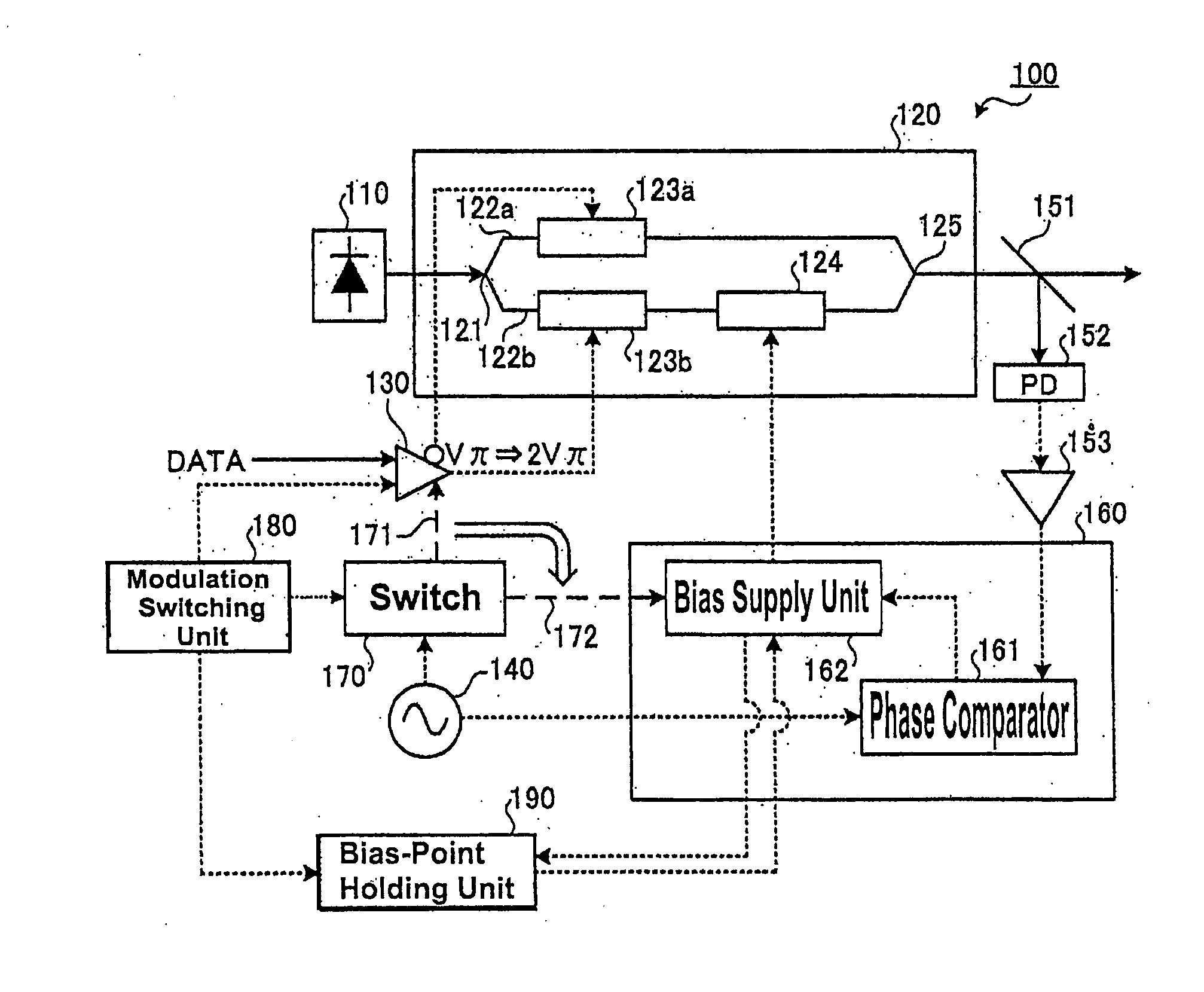
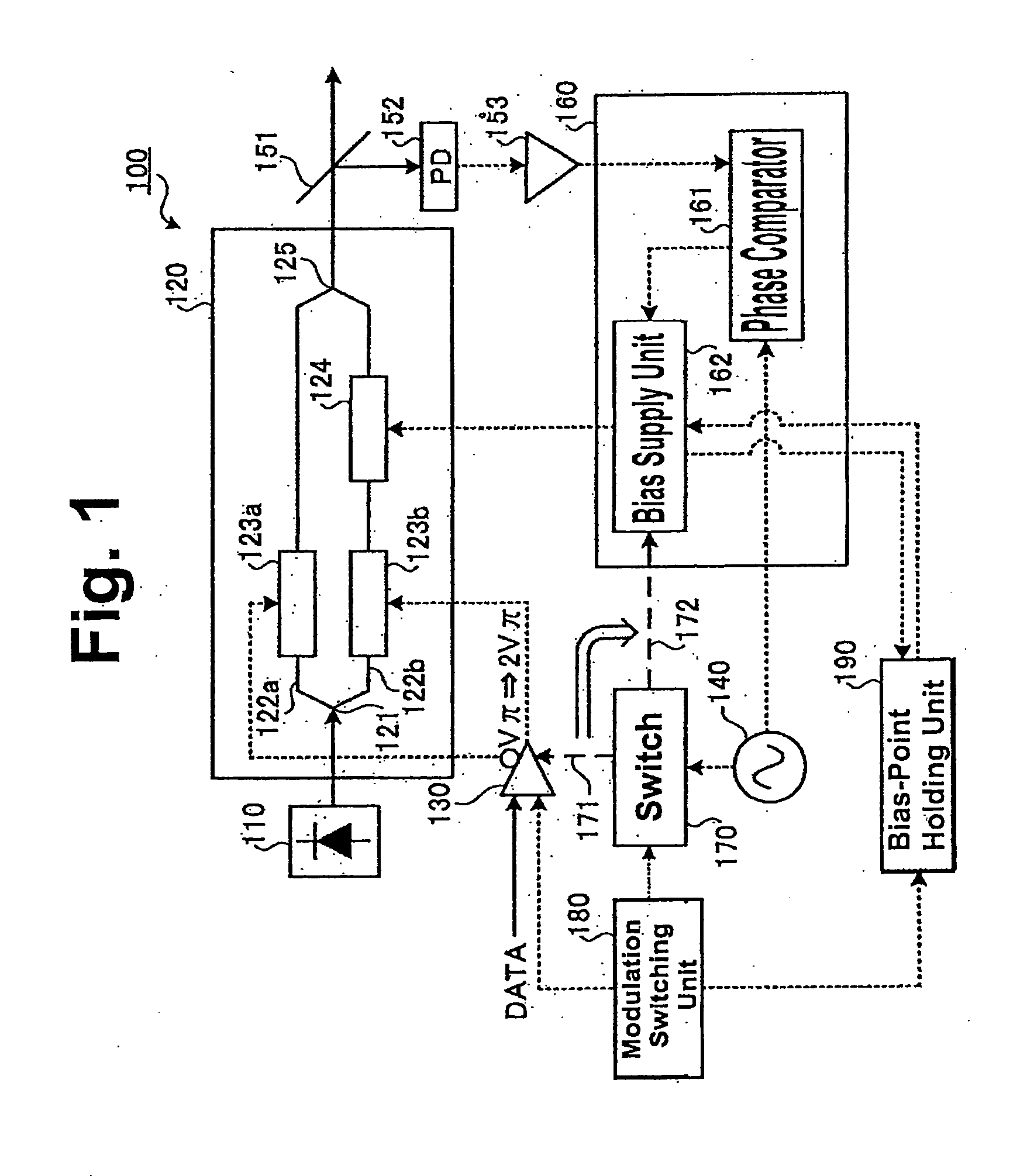
FIG. 1 is a block diagram showing the structure of an optical modulator according to the first embodiment. In FIG. 1, a solid arrow shows a light flow and a dotted arrow shows an electrical flow (similarly in the following block diagrams). An optical modulation device 100 according to the first embodiment is an optical modulator that can switch the DPSK and the NRZ intensity modulation format in accordance with modulation switching information.

Referring to FIG. 1, the optical modulation device 100 comprises: a light source 110; a Mach-Zehnder modulator (MZ modulator) 120; a driving unit (driving circuit) 130; an oscillator 140; a branch unit 151; a light receiving unit 152 (PD); an amplifying unit 153; a bias control unit 160; a switch 170; a modulation switching unit (controller) 180; and a bias-point holding unit 190. The light source 110 generates continuous light as carrier light and outputs the generated continuous light to the MZ modulator 120.

The MZ modulator 120 performs NRZ...

second embodiment

FIG. 7 is a block diagram showing the structure of an optical modulator according to the second embodiment. Referring to FIG. 7, the same component as that shown in FIG. 1 is designated by the same reference numeral and a description thereof is omitted. An optical modulation device 100 according to the second embodiment can switch RZ modulation format (e.g., duty ratio is 50%) and non-modulation format in accordance with the modulation switching information. As an example, a description will be given of the optical modulation device 100 that can switch RZ-DQPSK and DQPSK.

Referring to FIG. 7, the optical modulation device 100 according to the second embodiment comprises: a MZ modulator 700; a driving unit 740A; a driving unit 740B; a branch unit 750; a light receiving unit 760; and a bias supply unit 770, in addition to the structure of the optical modulation device 100 according to the first embodiment. The MZ modulator 700 is a DQPSK modulator that performs differential quadrature ...

third embodiment

FIG. 10A is a block diagram showing the structure of a optical modulator according to the third embodiment. Referring to FIG. 10A, the same components as those shown in FIG. 7 are designated by the same reference numerals and a description thereof is omitted. An optical modulation device 100 according to the third embodiment can switch the RZ modulation format and CSRZ modulation format in accordance with the modulation switching information. As an example, a description will be given of the structure in which the optical modulation device 100 can switch the RZ-DQPSK and the CSRZ-DQPSK.

The MZ modulator 120 performs the RZ modulation or the CSRZ modulation of the signal light subjected to the DQPSK output from the branch unit 750. Further, the MZ modulator 120 switches the RZ modulation / CSRZ modulation in accordance with the modulation switching information. Referring to FIG. 10A, the optical modulation device 100 according to the third embodiment comprises a frequency converting uni...


PUM


Abstract

According to an aspect of an embodiment, an optical modulation device includes a Mach-Zehnder modulator and a controller. The Mach-Zehnder modulator is supplied a drive signal and a bias voltage. The Mach-Zehnder modulator modulates inputted light on the bases of the drive signal and the bias voltage. The drive signal selectively is superimposes a predetermined frequency signal. The bias voltage selectively is superimposes the predetermined frequency signal. The controller selects a superimposing target which is the drive signal or the bias voltage so as to change modulation formats.

Description

BACKGROUND OF THE INVENTIONThe present invention relates to an optical modulator using a Mach Zehnder modulator and a light-modulation switching method.Recently, in association with a rapid increase in amount of information, large capacity and long distance of an optical communication system is required. For example, an optical amplification repeating system of 40 Gb / s has been put into practical use. In the future, the larger capacity and the long distance will be further required. A TDM (Time Division Multiplexing) system and a WDM (Wavelength Division Multiplexing) system have been researched and developed.With respect to an electro-optical modulator circuit in an optical communication system, an intensity modulation (direct modulation) is the most simple. In this modulation, light emission / quenching is controlled by directly turning on / off current flowing to a semiconductor laser in response to “0” and “1” of a data signal. However, the laser is directly turned on / off and the pr...

Claims


Application Information

Patent Timeline
IPC IPC(8): G02F1/03H04B10/07H04B10/516H04B10/524H04B10/54H04B10/556H04B10/588H04B10/61
CPCG02F1/2255H04B10/505G02F1/0123H04B10/5167H04B10/5561H04B10/5162
Inventor TANAKA, TOSHIKIMIYATA, HIDEYUKIAKIYAMA, YUICHIHOSHIDA, TAKESHI
Owner FUJITSU LTD
Why Eureka
Try Eureka