Electric field poling of ferroelectric materials

a ferroelectric material and electric field technology, applied in the direction of optics, instruments, light guides, etc., can solve the problems of poor poling quality obtainable by controlled current techniques, achieve accurate control, improve poling quality, and improve poling quality

Active Publication Date: 2011-02-10
UNIV OF SOUTHAMPTON
View PDF4 Cites 2 Cited by
  • Summary
  • Abstract
  • Description
  • Claims
  • Application Information

AI Technical Summary

Benefits of technology

[0009]The method addresses the problem with conventional controlled voltage poling techniques of needing to know in advance the characteristics of the particular sample to determine a pre-known voltage to apply across the sample, by utilising a controlled current approach. It then further addresses problems with conventional current controlled poling by adding a pre-bias voltage that is applied to the sample before the poling process. Without a pre-bias voltage, the poling quality obtainable by controlled current techniques is poor. According to the invention, the pre-bias stabilises the sample at a voltage close to the coercive field before poling, which reduces the voltage increase that occurs when the poling current is initiated and the voltage has to rise to be larger than the coercive field. The voltage during poling is thereby much better defined, and the amount of charge delivered to the sample to produce domain inversion can be accurately controlled, giving greatly improved poling quality.
[0010]Any pre-bias voltage will give some enhancement over no pre-bias voltage, but the closer the pre-bias voltage is to the coercive field, the better the results. Therefore, embodiments of the invention propose that the pre-bias voltage is greater than 75% of the coercive field of the ferroelectric material, the pre-bias voltage is greater than 90% of the coercive field of the ferroelectric material, the pre-bias voltage is greater than 95% of the coercive field of the ferroelectric material, or the pre-bias voltage is greater than 99% of the coercive field of ferroelectric material.

Problems solved by technology

Without a pre-bias voltage, the poling quality obtainable by controlled current techniques is poor.

Method used


Image

  • Electric field poling of ferroelectric materials
  • Electric field poling of ferroelectric materials
  • Electric field poling of ferroelectric materials

Examples


Embodiment Construction

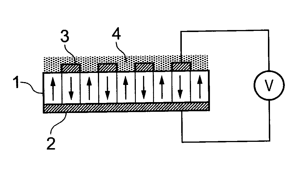
[0027]FIG. 1 is a simplified schematic representation of a ferroelectric substrate or wafer that has undergone periodic poling by application of an electric field, to illustrate the general principle of the technique. The substrate 1 has an electrode 2 continuously covering its lower face, and a patterned electrode 3 on its upper face. The patterned electrode 3 is configured as a plurality of parallel bands or stripes having widths and a mark-to-space ratio that correspond to the desired domain inversion spacing for the final poled crystal. A layer of insulating material 4 (liquid, gas, vacuum or photoresist, for example) overlays the patterned electrode to protect the substrate between the electrode stripes. A voltage V is applied across the substrate 1 using the electrodes 2, 3. Reversal of the ferroelectric domains occurs when the applied electric field exceeds the so-called coercive field for that ferroelectric material (being a property of the material). The patterning of the u...


PUM

PropertyMeasurementUnit
thicknessaaaaaaaaaa
resistanceaaaaaaaaaa
timeaaaaaaaaaa

Abstract

A method of inducing a periodic variation of nonlinearity value in a sample of ferroelectric material comprises arranging a pair of electrodes on opposite faces of the sample, one electrode defining a desired pattern of nonlinearity variation, applying a pre-bias voltage across the sample for a predetermined time using the electrodes, the pre-bias voltage being less than the coercive field of the ferroelectric material; and after the predetermined time, applying a current-controlled poling voltage across the sample using the electrodes, to produce domain inversion in the sample according to the desired pattern of nonlinearity variation. The pre-bias voltage may be 75% of the coercive field or more, and applied for a pre-determined time between 1 and 100 seconds.

Description

BACKGROUND OF THE INVENTION[0001]The present invention relates to an improved method for electric field poling of ferroelectric materials and apparatus for carrying out such a method.[0002]Nonlinear optical devices are proving very useful in the field of optics for converting laser light between different wavelengths. Examples of conversion include second harmonic generation in which two photons combine to create a new photon at twice the frequency (half the wavelength), and optical parametric generation in which a single photon splits into two photons at longer wavelengths. In general, such processes must conserve photon energy and must be phase-matched to achieve useful efficiencies. The requirement for phase-matching is that the phase velocities of the interacting waves in the nonlinear material must be equal. One phase-matching technique makes use of birefringence in a crystalline material to achieve efficient interaction. An alternative technique is based on the concept of quas...

Claims


Application Information

Patent Timeline
Patent Type & Authority Applications(United States)
IPC IPC(8): G02F1/355
CPCG02F1/3558G02F2202/07G02F2001/3548G02F1/3548
Inventor GAWITH, CORIN BARRY EDMUNDMAJOR, HUW EDWARDMING, LUSMITH, PETER GEORGE ROBIN
Owner UNIV OF SOUTHAMPTON
Why Eureka
Try Eureka