Electromagnetic wave oscillating devices

a technology of electromagnetic waves and oscillating devices, which is applied in the direction of instruments, light demodulation, non-linear optics, etc., can solve the problems of difficult to improve the output power of terahertz wave, difficult to control the intersecting angle of the pump and idler wave irradiated from laser light sources or optical fibers, etc., and achieves high output power

Active Publication Date: 2011-02-10
NGK INSULATORS LTD
View PDF6 Cites 13 Cited by
  • Summary
  • Abstract
  • Description
  • Claims
  • Application Information

AI Technical Summary

Benefits of technology

[0020]The inventors provided the guide waveguides for the pump and idler waves independently on the side of the incident face of the oscillating substrate of a non-linear optical crystal, so that the directions of propagation of the pump and idler waves can be precisely controlled at the end of the interacting part side of the waveguides. According to the construction, it is enough that the ends of the respective waveguides on the incident face side are optically and precisely aligned with outer optical fibers or with light sources, and th

Problems solved by technology

As a result, when the laser light sources or optical fibers are provided and optically connected to the incident face, it is difficult to control the intersecting angle α of the pump and idler w

Method used


Image

  • Electromagnetic wave oscillating devices
  • Electromagnetic wave oscillating devices
  • Electromagnetic wave oscillating devices

Examples


##ventive example 1

Inventive Example 1

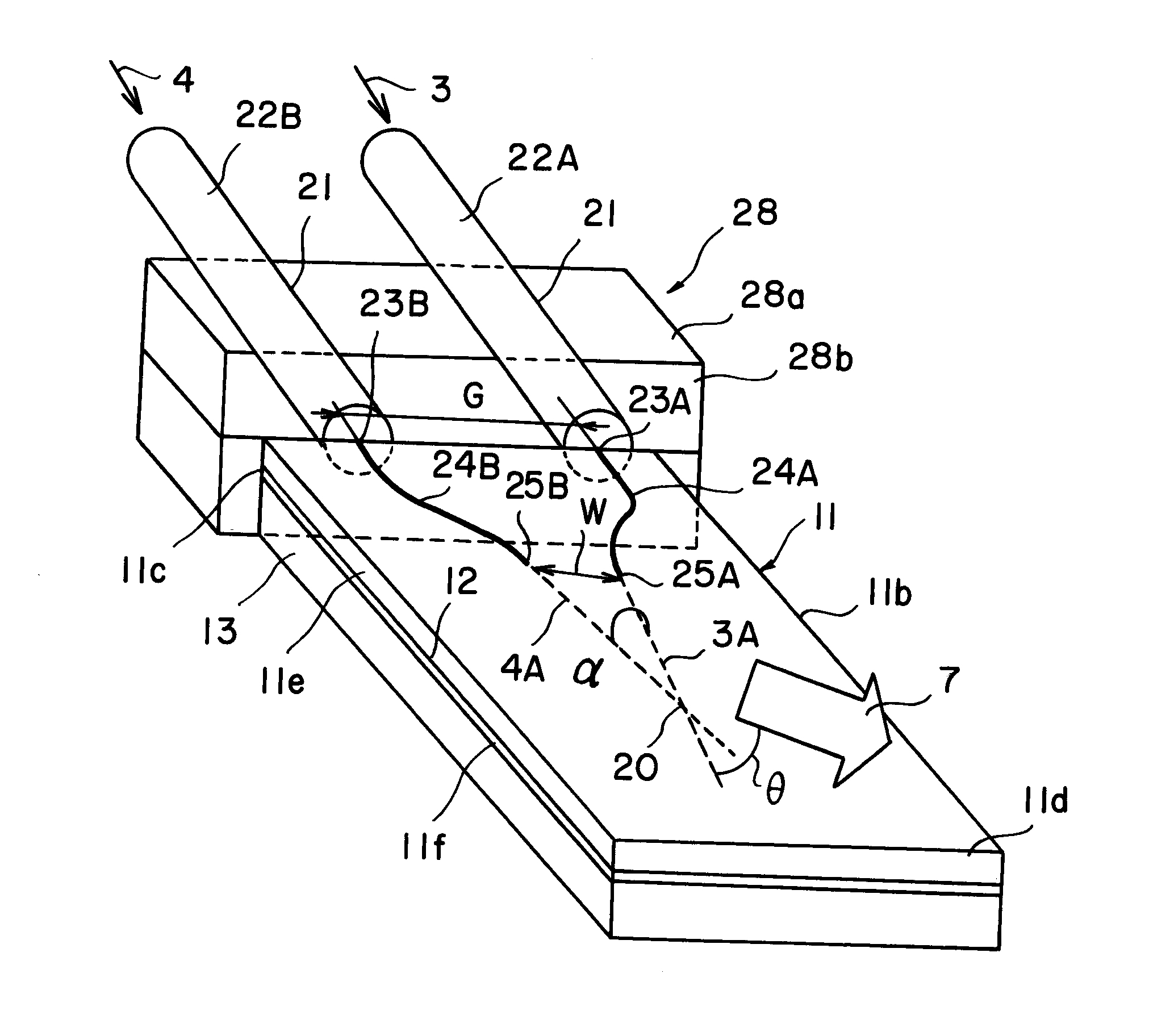
[0075]The oscillating device is produced similarly as the Reference Example. However, as shown in FIG. 7, the waveguides 24A and 24B are produced by titanium inner diffusion. Further, the optical fiber array was connected and aligned to the optical fibers. The pump and idler waves were connected to the optical fibers. The length of the device was made 50 mm. The oscillating substrate was made of lithium niobate single crystal and the thickness was made 10 μm. W was changed in a range of 40 to 250 μm and G was made 250 μm. The idler wave was made a wavelength valuable laser to change the wavelength to generate the terahertz wave having a wavelength of 0.11 THz to 0.7 THz. In the case that the length of the device was 10 mm, W was changed similarly to confirm the generation of the terahertz wave having a wavelength of 0.11 THz to 3 THz. Further in the case that the length of the device was 30 mm, the terahertz wave having a wavelength of 0.11 THz to 1 THz was succes...

##ventive example 2

Inventive Example 2

[0076]The oscillating device is produced similarly as the Reference Example. However, as shown in FIG. 8, the waveguides 24A and 24B are produced by titanium inner diffusion. The semiconductor laser light sources for the pump and idler waves were connected and aligned by butt joint. The length of the device was made 50 mm. The oscillating substrate was made of lithium niobate single crystal and the thickness was made 8 μm. W was changed in a range of 40 to 250 μm as the Inventive Example 1. G was made 1 mm. The idler wave was made a wavelength valuable laser to change the wavelength to generate the terahertz wave having a wavelength of 0.11 THz to 3 THz. In the case that the length of the device was 10 mm or 30 mm, the generation of the terahertz wave could be confirmed in a similar manner.


PUM


Abstract

An oscillating device includes an oscillating substrate 11 of a non-linear optical crystal and having an incident face 11c where a pump wave 3 and an idler wave 4 are made incident; a first waveguide 24A provided in the oscillating substrate 11 and between the incident face 11c and an interacting part 20 of the pump wave 3 and idler waves 4; and a second waveguide 24B provided in the oscillating substrate 11 and between the incident face 11c and the interacting part 20. The first waveguide 24A guides the pump wave 3 and the second waveguide 24B guides the idler wave 4.

Description

[0001]This application claims the benefit of Japanese Patent Application P2009-185772 filed on Aug. 10, 2009, the entirety of which is incorporated by reference.TECHNICAL FIELD[0002]The present invention relates to a device of oscillating so-called terahertz wave.BACKGROUND ARTS[0003]Terahertz waves are electromagnetic waves generally having a frequency of 0.1 THz to 10 THz, and are expected for basic fields such as physical properties, electrospectroscopy, bioscience, chemistry and pharmaceutical science and for applied fields of atmospheric environmental assessment, security, material test, food test and communication.[0004]As a device for oscillating terahertz waves, it has been developed a backward wave oscillator (BOW) and photomixing in several hundreds GHz band and free electron energy laser, p-Ge laser and quantum cascade laser (QCL) for 1 THz or more. These devices, however, have problems in the miniaturization and improvement of output power.[0005]On the other hand, it has...

Claims


Application Information

Patent Timeline
IPC IPC(8): G02F1/39G02F1/355
CPCG02F2203/13G02F1/39
Inventor KONDO, JUNGOAOKI, KENJIIWATA, YUICHIEJIRI, TETSUYA
Owner NGK INSULATORS LTD
Why Eureka
Try Eureka