Passive all-fiber integrated high power coherent beam combination

Active Publication Date: 2011-02-10
NORTHROP GRUMMAN SYST CORP
View PDF39 Cites 66 Cited by
  • Summary
  • Abstract
  • Description
  • Claims
  • Application Information

AI Technical Summary

Problems solved by technology

A design challenge for fiber laser amplifiers is to combine the beams from each fiber in a coherent manner so that the beams ...

Method used


Image

  • Passive all-fiber integrated high power coherent beam combination
  • Passive all-fiber integrated high power coherent beam combination
  • Passive all-fiber integrated high power coherent beam combination

Examples


Embodiment Construction

[0035]The following discussion of the embodiments of the disclosure directed to fiber laser amplifiers including tapered fiber bundles is merely exemplary in nature, and is in no way intended to limit the invention or its applications or uses.

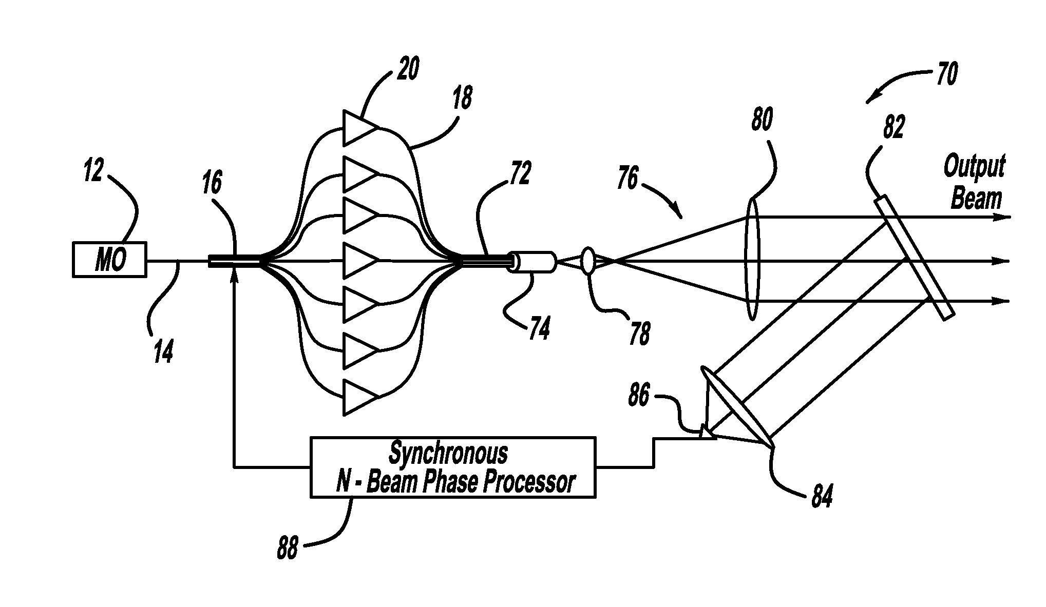
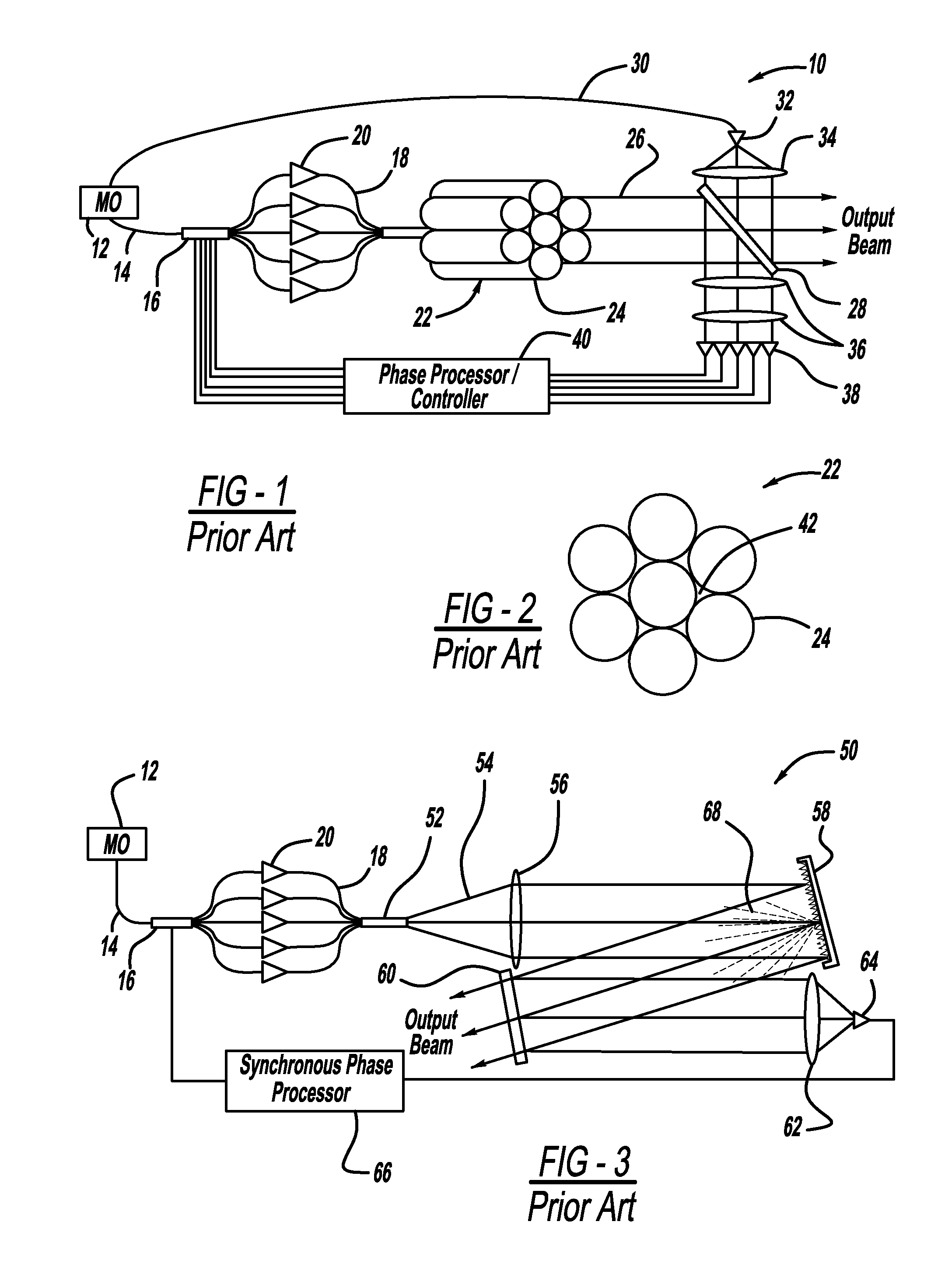
[0036]FIG. 1 is a schematic plan view of a known fiber laser amplifier system 10 including a master oscillator (MO) 12 that generates a signal beam on optical fiber 14. A fiber laser amplifier system of the type shown in FIG. 1 can be found in U.S. Pat. No. 6,708,003 issued Mar. 16, 2004 to Wickham et al., titled Optical Energy Transmission System Utilizing Precise Phase and Amplitude Control, assigned to the assignee of this application and herein incorporated by reference. The signal beam is spilt into a certain number of split beams by a splitter and phase modulators 16, where a separate phase modulator 16 is provided for each split beam. The splitter and the phase modulator are actually two separate devices, but shown here is a single objec...


PUM


Abstract

A fiber laser amplifier system including a beam splitter that splits a feedback beam into a plurality of fiber beams where a separate fiber beam is sent to a fiber amplifier for amplifying the fiber beam. A tapered fiber bundle couples all of the output ends of all of the fiber amplifiers into a combined fiber providing a combined output beam. An end cap is optically coupled to an output end of the tapered fiber bundle to expand the output beam. A beam sampler samples a portion of the output beam from the end cap and provides a sample beam. A single mode fiber receives the sample beam from the beam sampler and provides the feedback beam.

Description

BACKGROUND 1. Field of the Disclosure[0001]This disclosure relates generally to a high power fiber laser amplifier and, more particularly, to a high power fiber laser amplifier that couples ends of the fiber amplifiers into a tapered fiber bundle to combine the beams with improved fill factor.[0002]2. Discussion of the Related Art[0003]High power laser amplifiers have many applications, including industrial, commercial, military, etc. Designers of laser amplifiers are continuously investigating ways to increase the power of the laser amplifier for these applications. One known type of laser amplifier is a fiber laser amplifier that employs doped fibers and pump beams to generate the laser beam. Typically, a high power fiber laser amplifier uses a fiber that has an active core diameter of about 10-20 μm or larger. Modern fiber laser amplifier designs have achieved single fiber power levels up to 5 kW. Some fiber laser systems employ multiple fiber laser amplifiers and combine them in...

Claims


Application Information

Patent Timeline
IPC IPC(8): H01S3/067H01S3/10
CPCG02B6/02042G02B6/04G02B6/32H01S3/005H01S3/06729H01S3/10061H01S3/06745H01S3/06754H01S3/1307H01S3/2383H01S3/2391H01S3/06737
Inventor ROTHENBERG, JOSHUA ELLIOTTCHEUNG, ERIC CHIU TAT
Owner NORTHROP GRUMMAN SYST CORP
Why Eureka
Try Eureka