
Block Piece for Holding an Optical Workpiece, in Particular a Spectacle Lens, for Processing Thereof, and Method for Manufacturing Spectacle Lenses According to a Prescription

a technology for spectacle lenses and workpieces, applied in the field of workpiece support blocks, can solve the problems of time-consuming and laborious manual operations, the proposed lens block is not intended or suitable for coating processes, and the particular vacuum coating process, etc., and achieves the effects of reducing cost, high optical quality, and producing more quickly

Active Publication Date: 2011-02-10
SATISLOH AG
View PDF22 Cites 25 Cited by
  • Summary
  • Abstract
  • Description
  • Claims
  • Application Information

AI Technical Summary

Benefits of technology

The object of the present invention is to provide a block piece for holding an optical workpiece, in particular a spectacle lens, for processing thereof, which block piece serves to solve the drawbacks previously cited of the techniques known in the art and enables in particular spectacle lenses with high optical qualities to be produced more quickly and at lower cost, without restrictions as to the lens geometries usually processed in prescription workshops. The object of the invention further encompasses the provision of a method for manufacturing spectacle lenses according to a prescription that serves the above purposes.
Finally, it is preferred for the blocking face of the lens blank to be fully finished prior to the above blocking step (i), including hard coating, antireflection coating and, if required, top coating such as hydrophobic and / or oleophobic and / or dust repelling coating. In this instance the blocked spectacle lens blank could advantageously be shipped from the lens manufacturer to the prescription workshop where only the second face and, if required, the edge of the lens blank would need to be processed to obtain a spectacle lens ready for insertion into / mounting to the spectacle frame, wherein the first face of the lens blank would be protected by the block piece until the finished spectacle lens is deblocked. This approach would also minimize the production efforts in the prescription workshop.

Problems solved by technology

One disadvantage of the conventional overall process as outlined above consists in the fact that the spectacle lens blank needs to be deblocked after surfacing prior to coating, and then again blocked after coating prior to edging, for this requiring manual operations that are time-consuming and labor-intensive.
The proposed lens block however is not intended or suitable to be used in coating processes, in particular vacuum coating processes.
Although this document generally mentions that the lens can remain on the block piece during a coating process, it does not disclose or address how this could be done in a vacuum coating process in which the lens is subjected to a vacuum of, e.g., 5*10−3 mbar.
It can be expected that liquids from the surfacing and cleaning processes will remain in particular in the “equalizing and pressure medium channels” provided in the proposed block piece, which liquids can excessively prolong the time required to reach, if at all, the necessary vacuum and in addition may lead to impure coating conditions resulting in an imperfect coating.
Another problem with the conventional overall process as outlined above is that, in particular if the block piece is made from a plastic material, and the block piece is supported in the surfacing machine(s) by means of a collet chuck or the like which applies a radial compression force thereon, the block piece may assume a shape other than that which it naturally assumes in the absence of these forces.
Such deformation may transfer to the spectacle lens blank blocked on the block piece so that the curve which is cut into the surface of the lens blank may become distorted when the block piece is removed from the chuck and the lens blank is deblocked from the block piece and resumes its natural shape.
This problem becomes particularly acute in the manufacture of free-form spectacle lenses requiring very precise tolerances.
Any slight distortion of the curve upon deblocking the spectacle lens from the block piece may take it out of the tolerance range of the particular prescription, thereby rendering it useless for its desired purpose and resulting in substantial waste.
Still another problem with the conventional process in prescription workshops is associated with in particular the single point diamond turning as the presently preferred fine cutting process for spectacle lens blanks made from plastic materials.
This surfacing process as such is susceptible to small, but unacceptable errors at the center of rotation of the lens blank that are typically caused by errors of machine and tool calibration, as explained in great detail in document EP 1 719 584 A1 by the same applicant.
This, coupled to certain limitations of the subsequent (flexible) polishing process, where it can be difficult to totally “clean up” or remove such center errors, have led to certain limitations in the amount of prism (i.e. surface tilt or shift with respect to the axis of rotation) permissible to cut and polish in such combined surfacing process.
Experiments have shown that it can be relatively easy to cut and polish surfaces having 2 to 3 degrees of prism at the center with accurate centers, however greater amounts of prism at the center can pose problems.
However, one disadvantage of this known approach consists in the fact that, if the lens blank is blocked with a greater amount of prism, say 7 or 8 degrees of prism, the thickness of the wedge-shaped layer of blocking material between lens blank and block piece strongly varies along the prism axis.
For this reason the amount of prism permissible to be blocked is also limited in the known approach.

Method used


Image

  • Block Piece for Holding an Optical Workpiece, in Particular a Spectacle Lens, for Processing Thereof, and Method for Manufacturing Spectacle Lenses According to a Prescription
  • Block Piece for Holding an Optical Workpiece, in Particular a Spectacle Lens, for Processing Thereof, and Method for Manufacturing Spectacle Lenses According to a Prescription
  • Block Piece for Holding an Optical Workpiece, in Particular a Spectacle Lens, for Processing Thereof, and Method for Manufacturing Spectacle Lenses According to a Prescription

Examples


Embodiment Construction

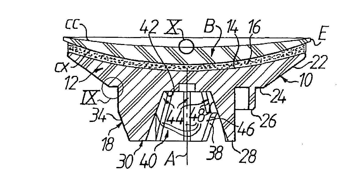
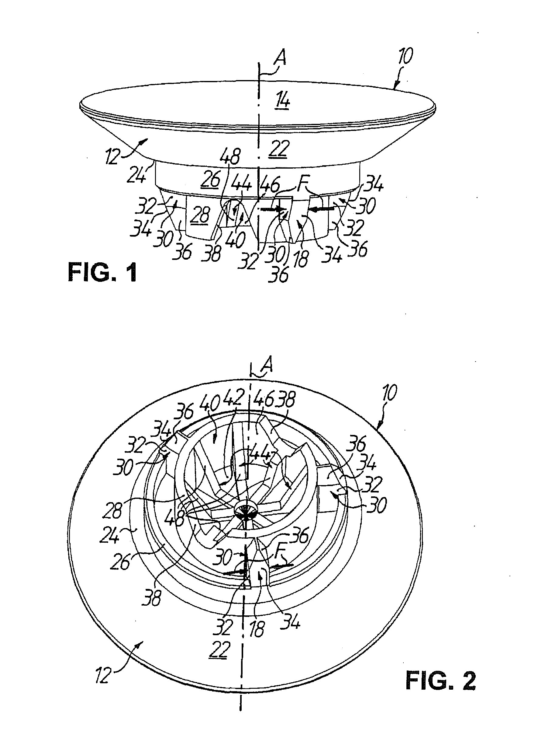
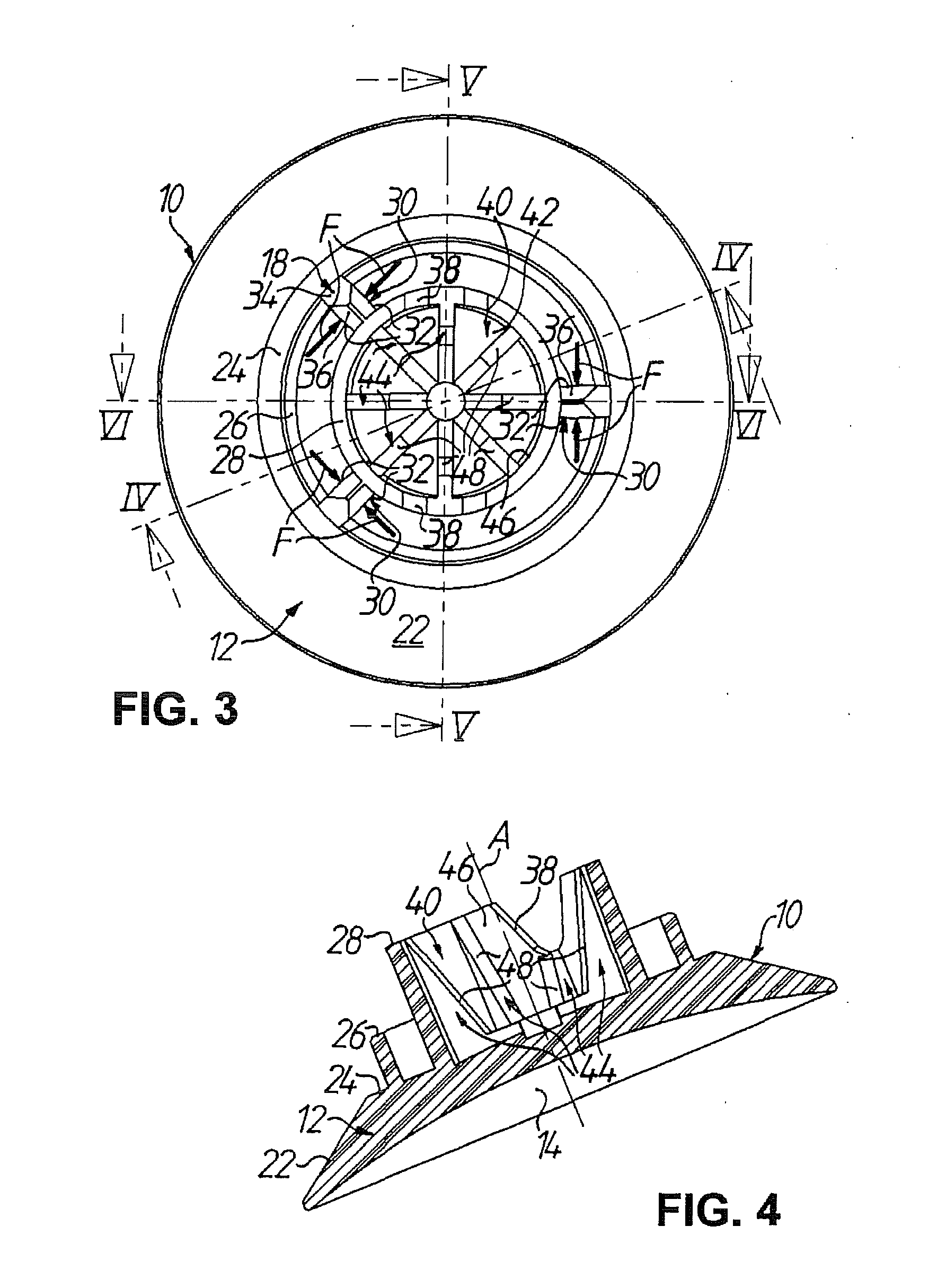
FIGS. 1 to 6 show a block piece 10 for holding an optical workpiece, in particular a spectacle lens blank B (cf. FIGS. 7 and 8), for processing thereof. The block piece 10 comprises a basic body 12 that has a workpiece mounting face portion 14 against which the spectacle lens blank B can be blocked by means of a blocking material 16 (see FIG. 8), preferably a UV and / or VIS curable adhesive blocking composition as disclosed in the earlier European patent application 07 013 158.6 by the same applicant. The basic body 12 of the block piece 10 further comprises a clamping portion 18 via which the spectacle lens blank B blocked on the basic body 12 can be fixed in a machine or apparatus for processing (i.e. surfacing, coating, edging, tinting, cleaning, etc., as the case may be) of the spectacle lens blank B.

As to the material of the basic body 12 that allows the block piece 10 to be used in vacuum thin film coating processes, reference is made to the introductory portion of the descript...


PUM


Abstract

A block piece for holding a spectacle lens blank has a basic body with a workpiece mounting face portion against which the workpiece can be blocked with a blocking material, and a clamping portion via which the blocked workpiece can be fixed in a machine / apparatus for processing it. The basic body is made substantially of a material having a defined low water absorption and / or is sealed to at least reduce outgassing of water moisture under vacuum conditions, so that the block piece can be used also in vacuum coating processes. Alternatively or in addition, the clamping portion is constructed to be clamped by forces directed essentially perpendicular to the radial direction to cancel out each other and not deform the basic body, and / or the workpiece mounting face portion is provided with a predetermined amount of prism.

Description

TECHNICAL FIELD OF THE INVENTIONThe present invention generally relates to a workpiece support block (“block piece”) for supporting an optical workpiece during the processing thereof. In particular, the invention relates to a block piece for holding a spectacle lens for processing thereof according to the preamble portion of claim 1, as used in prescription workshops in masses, that is to say production workshops for manufacturing individual spectacle lenses from customary materials (mineral glass, polycarbonate, PMMA, CR 39, HI index, etc.) according to a prescription. The invention also concerns a method for manufacturing spectacle lenses according to a prescription, as outlined in the preamble portion of claim 20.BACKGROUND OF THE INVENTION AND PRIOR ARTAn ophthalmic lens blank generally has a first face with a pre-determined curvature and a second face, opposite the first face on which a desired surface contour is generated by a machining process. The overall process is generall...

Claims


Application Information

Patent Timeline
IPC IPC(8): B05D5/06B05C13/02B24B13/005
CPCB24B13/0057B29D11/00942B29D11/00009
Inventor BREME, FRANKJORDI, LAURENTMCPHERSON, EDWARDSCHAFER, STEFANSAVOIE, MARC
Owner SATISLOH AG
Learn More