System level power evaluation method

Inactive Publication Date: 2011-02-10
UPM RAFLATEC OY
View PDF6 Cites 30 Cited by
  • Summary
  • Abstract
  • Description
  • Claims
  • Application Information

AI Technical Summary

Benefits of technology

[0011]It is an object therefore of the present invention to provide a system level power estimation

Problems solved by technology

This was not her

Method used


Image

  • System level power evaluation method
  • System level power evaluation method
  • System level power evaluation method

Examples


Embodiment Construction

[0104]The invention will now be more clearly understood from the following description of some embodiments thereof, given by way of example only with reference to the accompanying drawings in which:

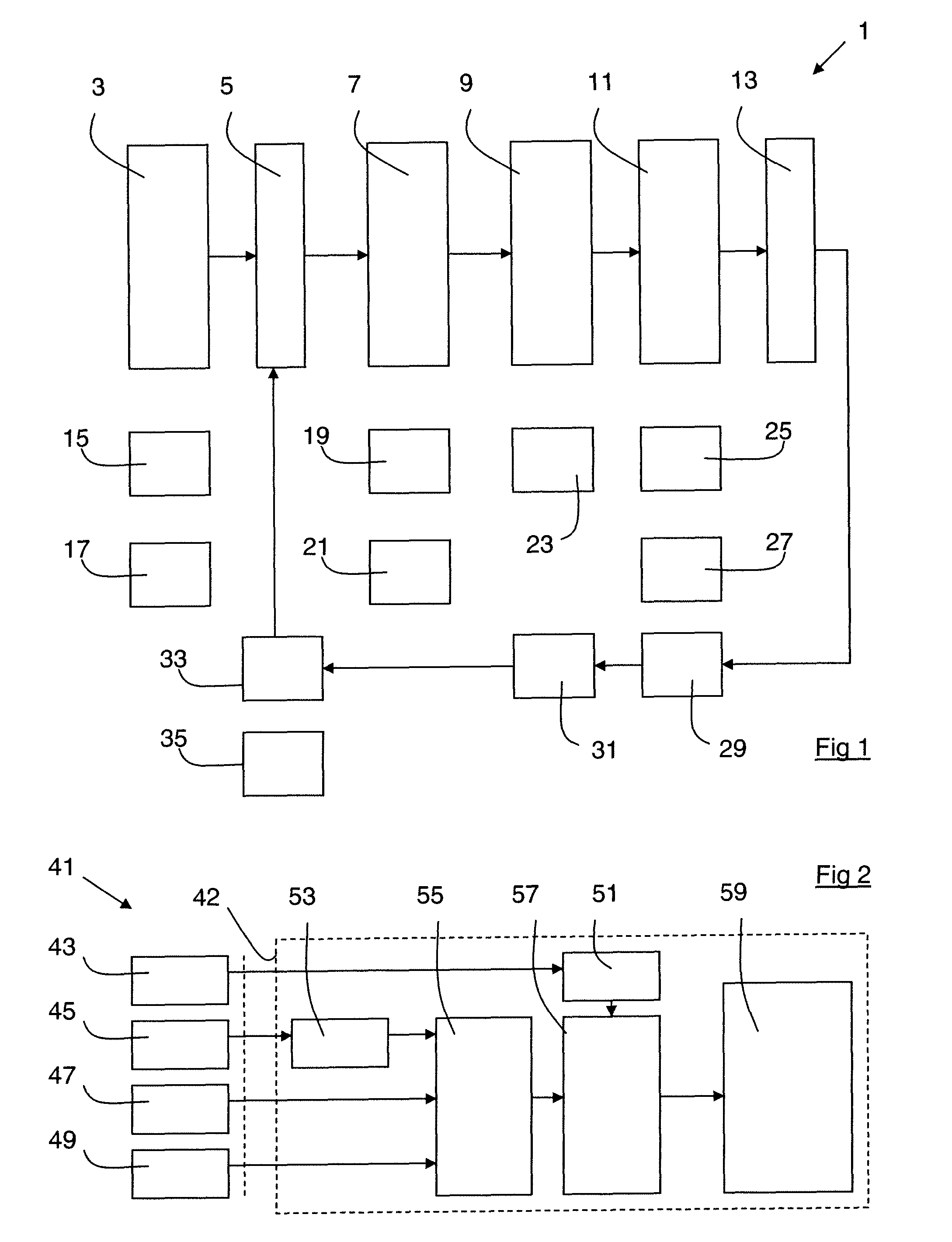
[0105]FIG. 1 is a diagrammatic representation of a parallel processor for logic event simulation (APPLES) according to the art;

[0106]FIG. 2 is a diagrammatic representation of a system incorporating an ENiGMA processor;

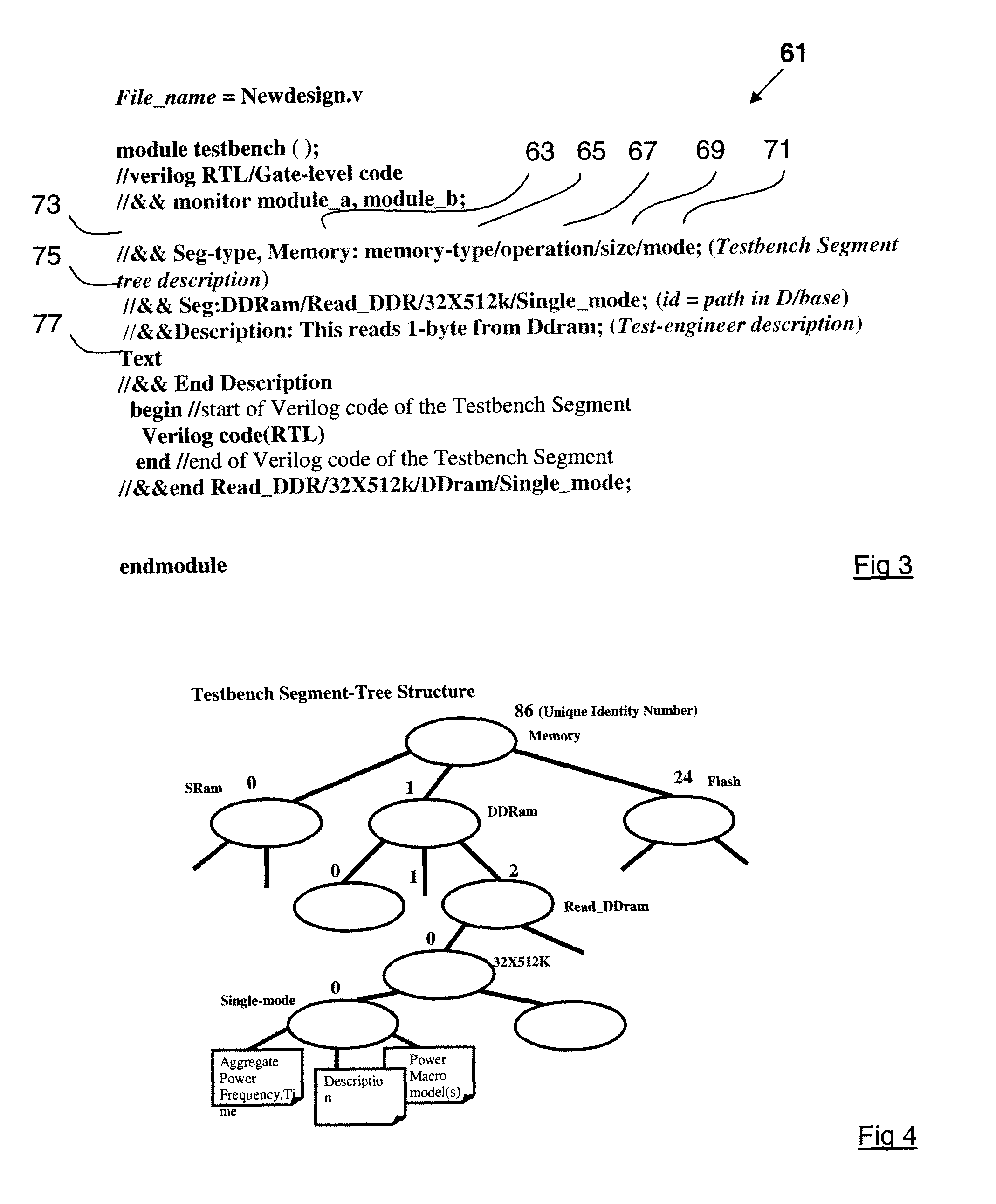
[0107]FIG. 3 is a diagrammatic representation of the definition and structure of a segment;

[0108]FIG. 4 is a diagrammatic representation of a Testbench Segment tree;

[0109]FIG. 5 is a diagrammatic representation of a monitor file;

[0110]FIG. 6 is a diagrammatic representation of the sequence in which the files are generated;

[0111]FIG. 7 shows active modules being monitored;

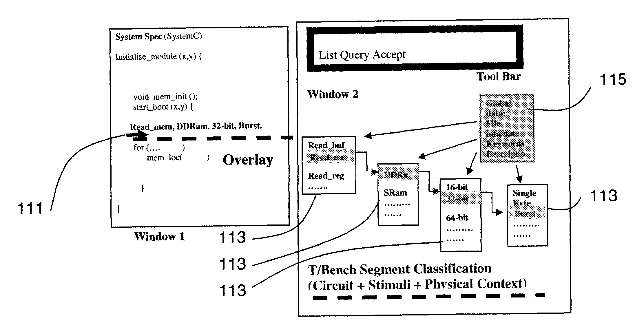
[0112]FIG. 8 shows a SystemC overlay insertion according to the present invention;

[0113]FIG. 9 shows a SystemC compile file according to the present invention;

[0114]FIG. 10 shows a power trace file accordin...


PUM


Abstract

This invention relates to a system level power evaluation method in which detailed power macro-models (PMM) are created for operations of modules. These PMMs are stored in memory. A system level circuit description (SLCD) is evaluated using the PMMs stored in memory that are relevant to that SLCD and using other PMMs that are generated for operations of modules that do not have PMMs stored in memory. In this way, a highly accurate and computationally efficient power evaluation of the SLCD is possible. Furthermore, the user implementing the method may define a case, which relates to an operation of a module and has a PMM associated therewith, in a highly flexible manner that allows for more abstract analysis of the SLCD to be carried out. A case may relate to a single operation of a module, a plurality of operations of a module or operation(s) of a plurality of modules.

Description

INTRODUCTION[0001]This invention relates to a method of evaluating the power characteristics of a system level circuit description.[0002]One of the most important considerations when designing digital circuits and System on Chip (SoC) designs in particular is the power consumption of the design. It is highly desirable to minimise the power consumption of these designs. Heretofore, numerous power evaluation tools and methods have been proposed to accurately estimate the power consumption of digital circuit designs prior to the physical realisation of those designs. The vast majority of these power evaluation tools operate on a gate level design of the digital circuit.[0003]One such known method and tool is that described in PCT Publication No. WO2006 / 038207 (University College Dublin) entitled “A method and processor for power analysis in digital circuits”. This document describes a modified processor, otherwise referred to as the Energy Investigation for Gate and Module Analysis (EN...

Claims


Application Information

Patent Timeline
IPC IPC(8): G06F17/50
CPCG06F2217/78G06F17/5009G06F2119/06G06F30/20
Inventor DALTON, DAMIAN JUDEMCCARTHY, ANDREW JOHNQUIGLEY, ROBERT NEILSONLEENEY, HUGO MICHAEL
Owner UPM RAFLATEC OY
Why Eureka
Try Eureka