Thermodynamic power generation system

a power generation system and thermodynamic technology, applied in the direction of wind motors with parallel air flow, wind motors with perpendicular air flow, steam use, etc., can solve the problems of blades not working well for low pressure and temperature gasses

Inactive Publication Date: 2011-02-17
AMERICAN THERMAL POWER
View PDF52 Cites 60 Cited by
  • Summary
  • Abstract
  • Description
  • Claims
  • Application Information

AI Technical Summary

Benefits of technology

[0028]Briefly described, the present invention includes an externally heated engine contained within an enclosure. A rotating member is mounted within the enclosure on bearings, with a shaft that extends through a seal, to the outside of the engine. Mounted upon the rotating member are one or more blades. A flow of gasses is directed upon the surface of these blades by the action of one or more stationary nozzles. As a result of the action of the gasses upon the blades, force is exerted upon the blades. This causes the rotating member to revolve, and torque is exerted upon the shaft while it rotates.

Problems solved by technology

These blades do not function well for low pressure and temperature gasses.

Method used


Image

  • Thermodynamic power generation system
  • Thermodynamic power generation system
  • Thermodynamic power generation system

Examples


Embodiment Construction

[0079]FIGS. 1 through 11 describe the heat engine. FIGS. 12 through 15 describe the complete thermodynamic system.

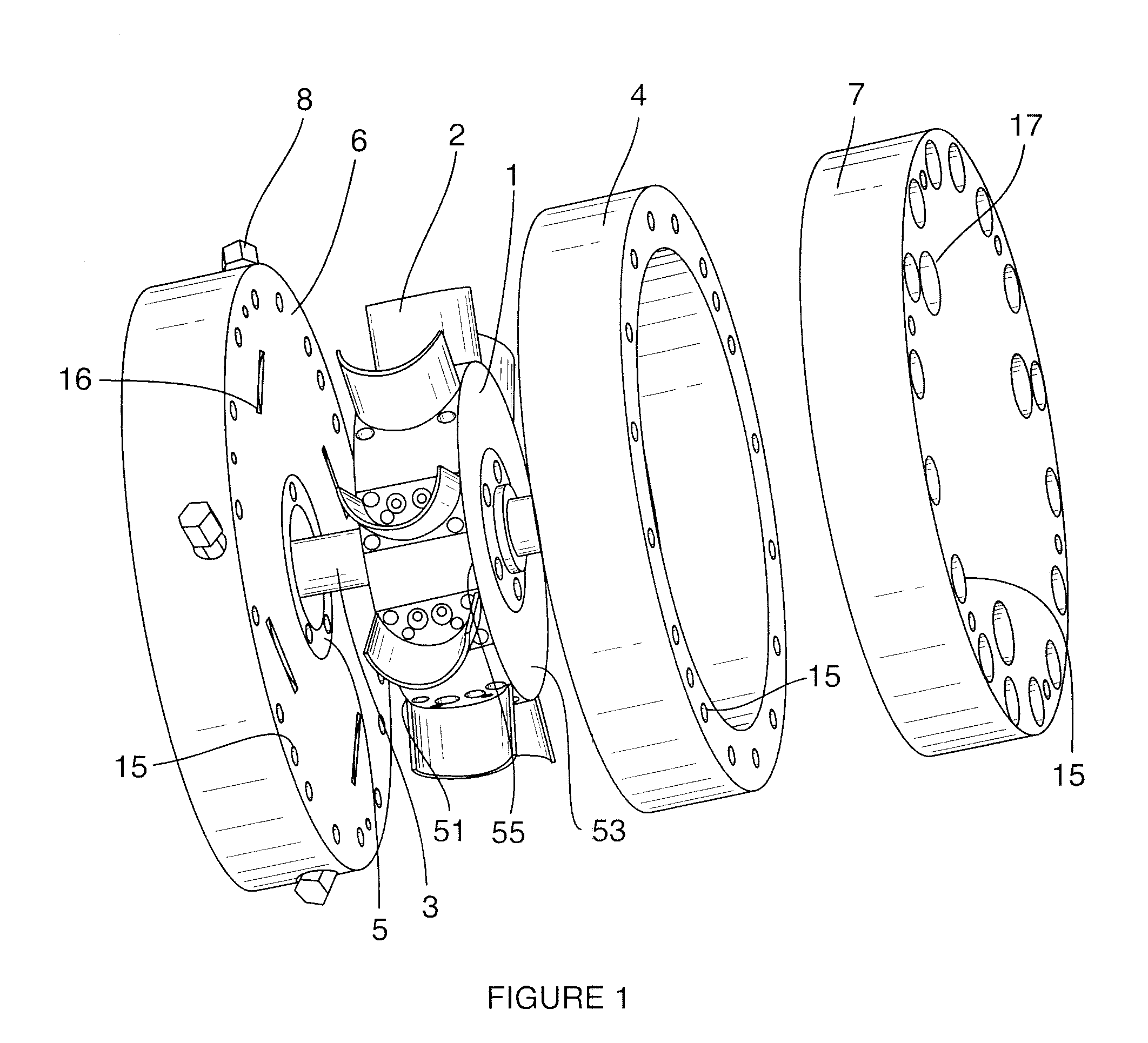
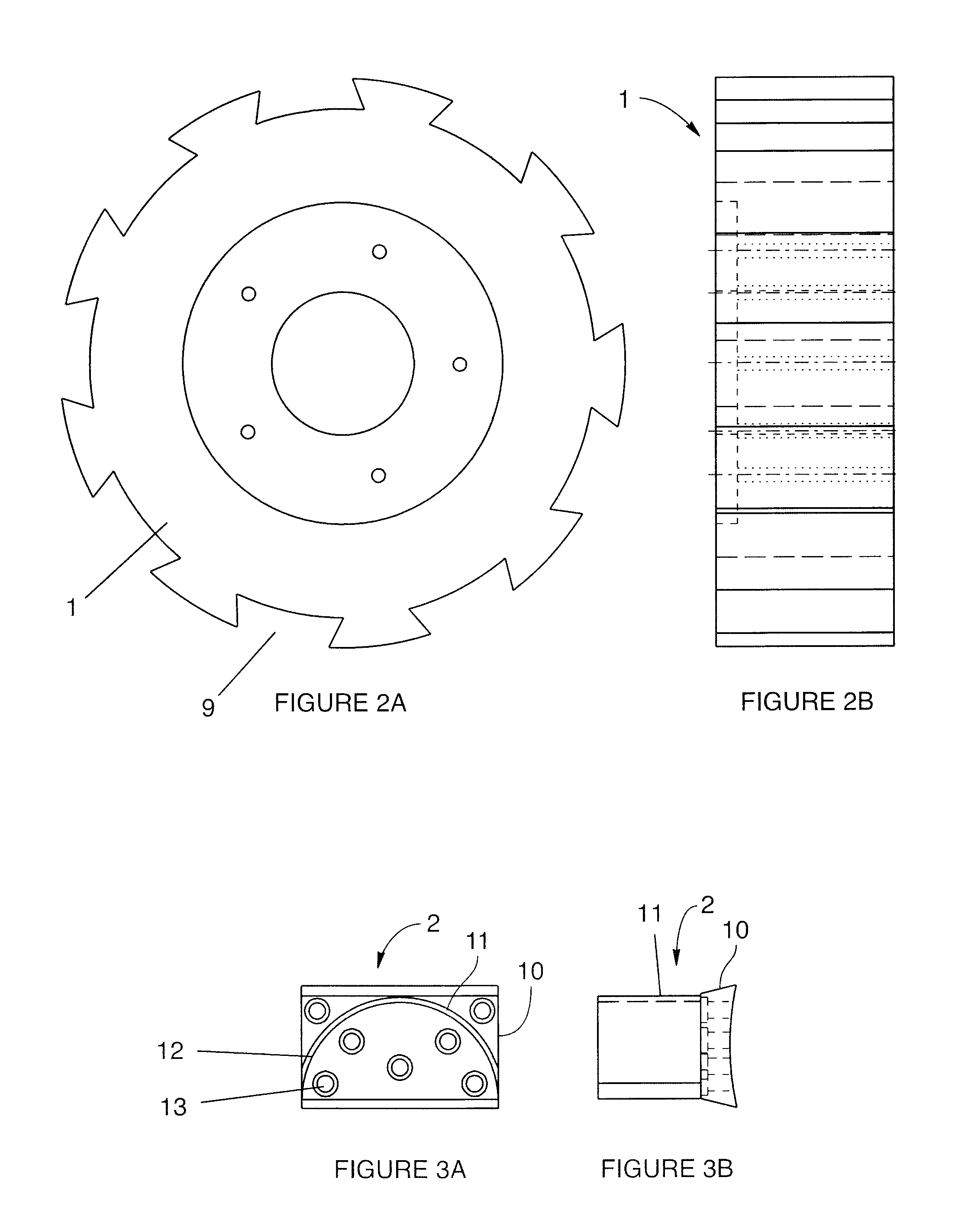
[0080]Beginning with the heat engine, FIG. 1 shows an exploded view of the heat engine components. As shown, the heat engine includes a left end bell 6, a right end bell 7, and a ring 4 that act together to enclose, seal, and support the engine. A rotating member 1 is mounted on a shaft 3, and the shaft 3 is supported by bearings 5 that are mounted in both left end bell 6 and right end bell 7. The shaft 3 is operatively connected to an electrical generator or other mechanical device to extract work from the rotating member 1. The left end housing includes inlet ports 16 each supporting a nozzle 8. The right hand bell 7 includes exhaust ports 17. While the invention is illustrated with four inlet nozzles, the number of inlet ports and corresponding nozzles can vary from one to many. The left end bell 6, the ring 4 and right end bell 7 are securely fastened together in a f...


PUM


Abstract

A power generation system that includes a heat source loop, a heat engine loop, and a heat reclaiming loop. The heat can be waste heat from a steam turbine, industrial process or refrigeration or air-conditioning system, solar heat collectors or geothermal sources. The heat source loop may also include a heat storage medium to allow continuous operation even when the source of heat is intermittent. Heat from the heat source loop is introduced into the heat reclaiming loop or turbine loop. In the turbine loop a working fluid is boiled, injected into the turbine, recovered condensed and recycled. The power generation system further includes a heat reclaiming loop having a fluid that extracts heat from the turbine loop. The fluid of the heat reclaiming loop is then raised to a higher temperature and then placed in heat exchange relationship with the working fluid of the turbine loop. The power generating system is capable of using low temperature waste heat is approximately of 150 degrees F. or less. The turbine includes one or more blades mounted on a rotating member. The turbine also includes one or more nozzles capable of introducing the gaseous working fluid, at a very shallow angle on to the surface of the blade or blades at a very high velocity. The pressure differential between the upstream and downstream surfaces of the blade as well as the change in direction of the high velocity hot gas flow create a combined force to impart rotation to the rotary member.

Description

CROSS REFERENCE TO RELATED APPLICATIONS[0001]This application is a continuation-in-part of U.S. patent application Ser. No. 12 / 708,088, entitled “Thermodynamic Power Generation System” filed on Feb. 18, 2010, which in turn claims the benefit of the filing date of U.S. Provisional Patent Application No. 61 / 154,020, filed on Feb. 20, 2009, the entire contents of which are herein incorporated by reference.FIELD OF THE INVENTION[0002]The present invention relates to externally heated engines. More particularly the invention relates to improvements in efficiency and performance of externally heated engines operating at low temperatures and pressures.BACKGROUND OF THE INVENTION[0003]Externally heated engines especially those similar to the gas or liquid turbine type engines have always held great promise. This is because such engines are reasonably efficient, relatively simple in their operation, and flexible in the media they can employ as working fluids. At the same time however, they h...

Claims


Application Information

Patent Timeline
Patent Type & Authority Applications(United States)
IPC IPC(8): F01K27/00F01D5/30F01D25/24F03G7/00F03G6/00
CPCF01D1/22F01D5/3007F01D5/326Y02E10/46F01K17/005F01K25/10F01K13/02Y02P80/20
Inventor WATERSTRIPE, ROBERT F.HOFFMAN, GARY P.WILLOUGHBY, RICHARD L.
Owner AMERICAN THERMAL POWER
Why Eureka
Try Eureka