Rotary electromagnetic machines

a technology of electromagnetic machines and rotating shafts, which is applied in the direction of dc commutators, ac commutators, electrical equipment, etc., can solve the problems of dangerous handling during the construction process of motors, practicable limitation of surface area, etc., and achieve the effect of increasing the reliability of motors or generators, and reducing the size and weight of such machines

Inactive Publication Date: 2011-02-17
DENNE PHILLIP RAYMOND MICHAEL
View PDF9 Cites 4 Cited by
  • Summary
  • Abstract
  • Description
  • Claims
  • Application Information

AI Technical Summary

Benefits of technology

[0026]Embodiments of the present invention seek to provide an economical means of constructing a rotary electrical machine in which the limitations on the diameter and mass of the individual magnets are overcome so that large torques and power outputs may be produced if required.
[0027]Furthermore, embodiments of the present invention seek to reduce the size and weight of such a machine.
[0028]The wireless electrical part of the machine consists in an assembly of patterned laminations of a conducting material (such as aluminium) that is wrapped around the axis of the armature within an outer cylinder of ferromagnetic material. It will be understood that, because each conductor lamination has a large area and replaces many individual coils and their interconnections by a single component, the use of the wireless technology increases the reliability of the motor or generator.

Problems solved by technology

This is not a simple matter, because there is a practical limitation on the surface area that is set by the need to sinter the most common form of permanent magnet material under great pressure.
As the unit size of a powerful permanent magnet is increased, it also becomes more dangerous to handle during the process of building the motor.

Method used


Image

  • Rotary electromagnetic machines
  • Rotary electromagnetic machines
  • Rotary electromagnetic machines

Examples


Embodiment Construction

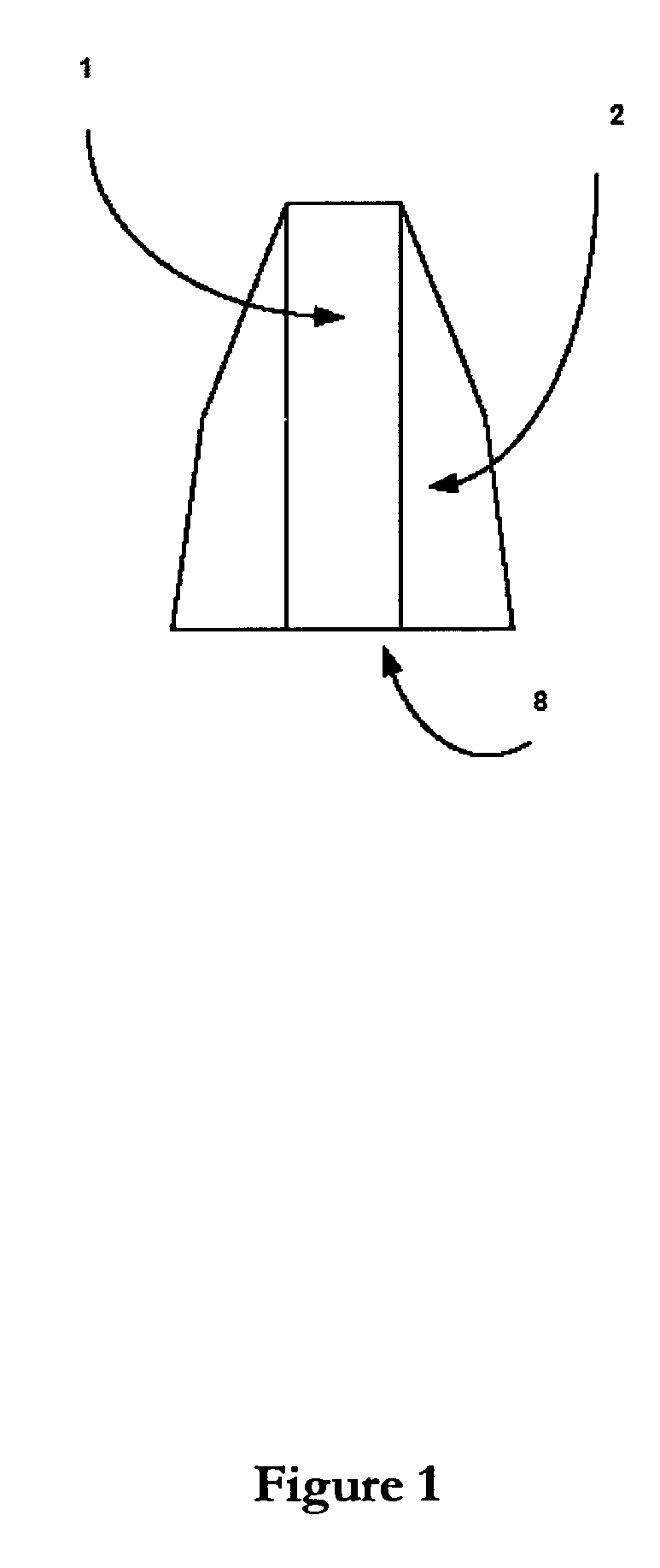
[0047]FIG. 1 schematically illustrates how magnets 1 are fitted between tapered pole pieces 2, so as to concentrate the flux and redirect it radially outwards via conducting laminations. It will be understood that the outer surfaces 8 of the magnet and polepieces (here shown flat) can be curved to conform to the bounding cylinder of the armature.

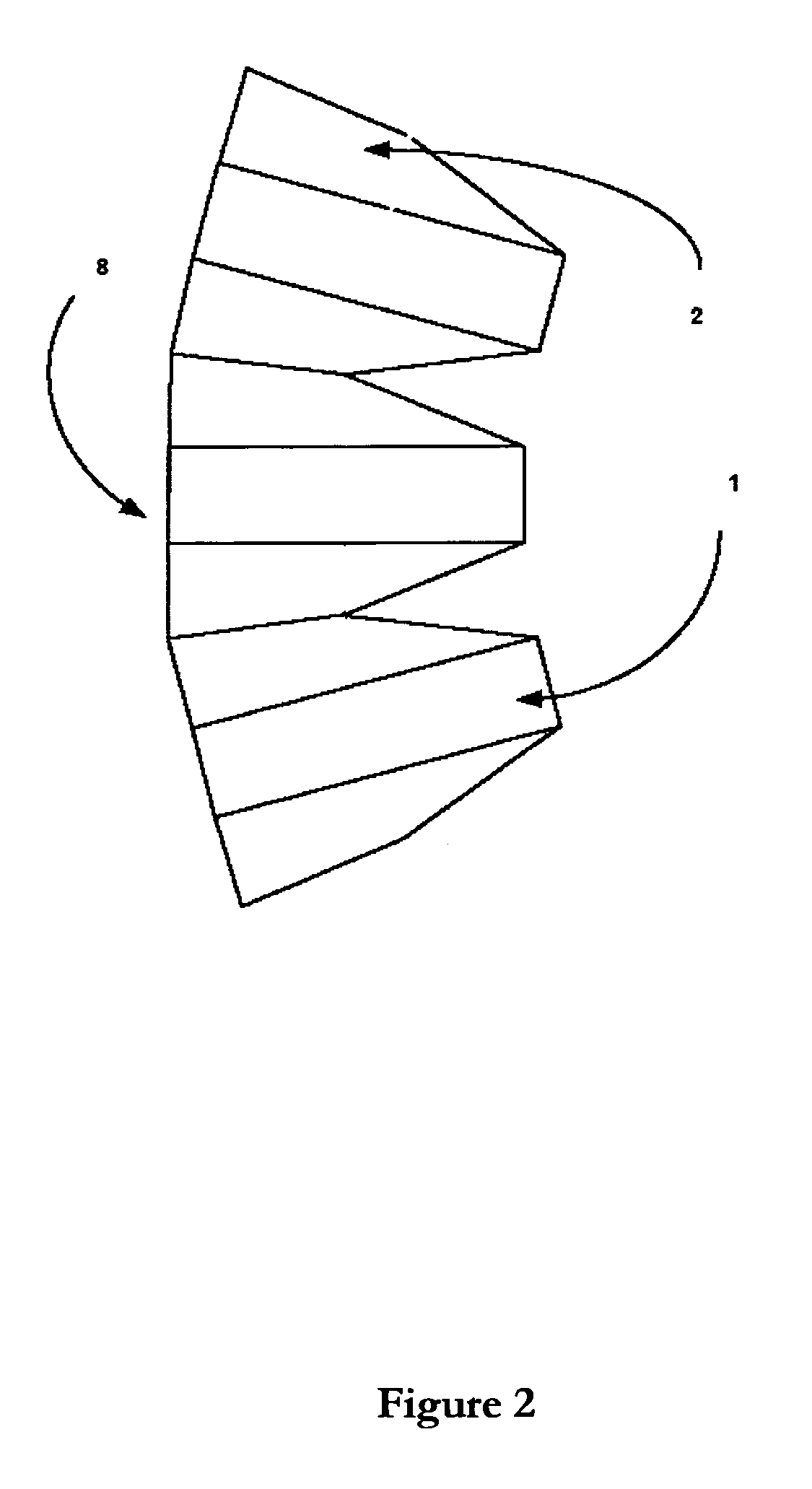
[0048]FIG. 2 shows how the force units of FIG. 1 may be abutted to encircle a torque tube (not shown). It will be understood that the taper angle of the pole piece is matched to the number of force units around the torque tube. Again, the outer facet edges 8 of the polepieces 2 and magnets 1 can also be curved to match the bounding cylinder of the armature.

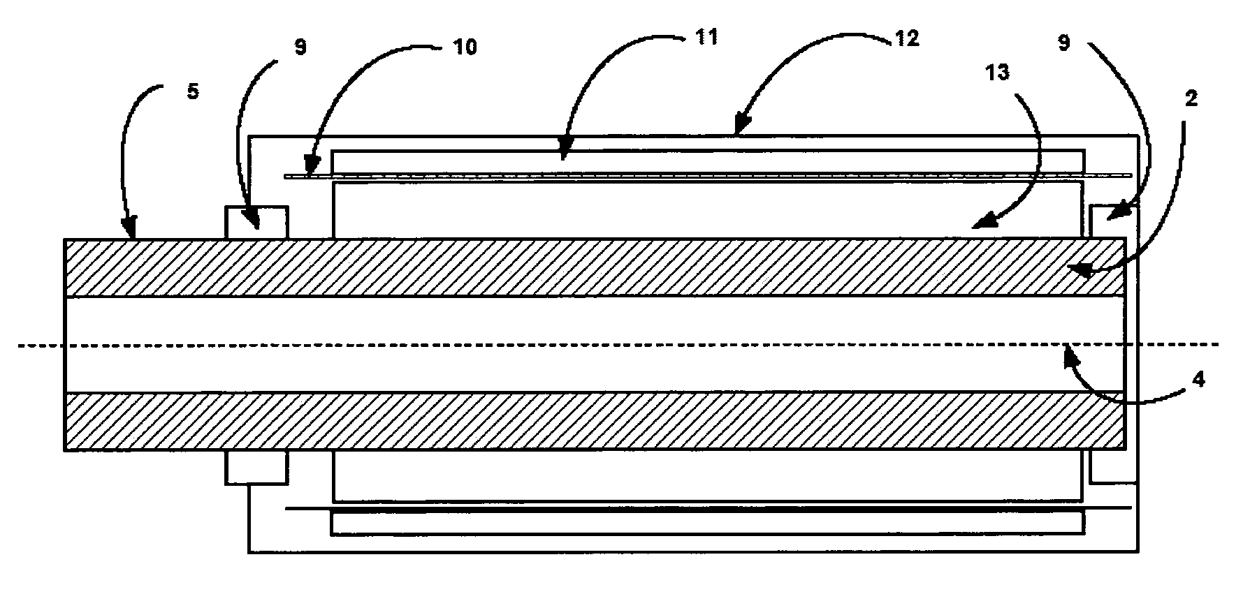
[0049]FIG. 3 shows an axial section of the armature, indicating how the magnets 1 are abutted along the length of each pole piece 2. Every force unit experiences a strong magnetostatic force radially outwards across the air gap and it is therefore necessary for the complete assembly to be ...


PUM


Abstract

A rotary electromagnetic machine is described which comprises first and second substantially cylindrical parts arranged to move relative to each other about a common axis. The first cylindrical part produces a spatially periodic radial magnetic field across an air gap, the magnetic field having a regular alternating polarity around the circumference of the first cylindrical part. The second cylindrical part comprises at least one laminar electrical conductor wrapped into cylindrical form and placed in the air gap to intercept the magnetic field, the laminar electrical conductor comprising a regular pattern of electrically conductive paths within the air gap. In more general terms, rotary motors in which the wire coils are replaced by laminations of material in which patterned conducting paths are created are described. The conducting laminations are placed in the air gap between an mature and backing iron that is constructed so as to reduce eddy current losses.

Description

FIELD OF INVENTION[0001]The present invention relates to a rotary electromagnetic machine, and more particularly to a rotary electromagnetic machine having cylindrical magnetic and electrical parts which move relative to each other to provide rotary motion.BACKGROUND OF THE INVENTION[0002]It is known to construct linear electric motors in a cylindrical form in which the output is a rod or tube. In such machines the magnetic part generally consists in an array of permanent magnets of disc form that produces a spatially-periodic radial magnetic field and the electrical part of such a linear motor consists in a stack of coils or electrical conductors that surround the armature along the axis of the machine and intersect the said spatially-periodic radial magnetic field. The whole assembly is generally contained within and bonded to a cylinder of mild steel that also acts as the backing iron by which the magnetic flux may complete its path. Machines of this kind are described in PCT / GB9...

Claims


Application Information

Patent Timeline
Patent Type & Authority Applications(United States)
IPC IPC(8): H02K3/26
CPCH02K3/26H02K41/03H02K3/47
Inventor DENNE, PHILLIP RAYMOND MICHAEL
Owner DENNE PHILLIP RAYMOND MICHAEL
Why Eureka
Try Eureka