
Stiffness compensation in opto-mechanical mechanisms

a technology of stiffness compensation and opto-mechanical assembly, which is applied in the direction of optical radiation measurement, instruments, spectrometry/spectrophotometry/monochromators, etc., can solve the problems of increased force required to maintain the angular position of the opto-mechanical assembly, waste of additional force, and indefinite operation life etc., to improve the reliability of the flexure bearing 602, improve the efficiency of the magnet arrangement, and reduce the net restoring torque ratio ratio

Active Publication Date: 2011-02-17
ABB INC
View PDF5 Cites 4 Cited by
  • Summary
  • Abstract
  • Description
  • Claims
  • Application Information

AI Technical Summary

Benefits of technology

[0028]an actuator coupled to the head to cause the head to move when the actuator is actuated;
[0034]coupling an actuator to the head to cause the head to move when the actuator is actuated;

Problems solved by technology

The operational life of flexure bearings can be indefinitely long when stresses in the flexure bearing blades are limited to below the endurance stress of the bearing material.
Thus the disadvantage of using flexure bearings for such assemblies is that increased force is required to maintain the angular position of the opto-mechanical assembly as the angle of rotation of the bearings is increased with respect to their rest position.
Further the actuators must also provide a force to overcome the flexure bearing restoring force or restoring torque and this additional force is wasteful.
However, one disadvantage of compensating for the restoring torque is that it eliminates the inherent advantage of the restoring torque to ease turnaround in scanning mechanisms.
Many factors may limit power consumption.
Examples of such factors are concern for the environment or indirectly Energy Star certification, battery capacity in satellite systems, and restrained operational temperatures to which power dissipation and thus consumption is an obstacle.
However, the mechanisms described in the above two articles have an obvious resemblance to the mechanism described in the CSEM Article and thus have the same flaw described above related to compression and extension and spring blades, namely, they both introduce low parasitic vibration frequencies with relatively high amplitude.
Also this restoring torque mechanism can only be used to compensate for the restoring torque arising from a rotational movement of a flexure bearing.

Method used


Image

  • Stiffness compensation in opto-mechanical mechanisms
  • Stiffness compensation in opto-mechanical mechanisms
  • Stiffness compensation in opto-mechanical mechanisms

Examples


Embodiment Construction

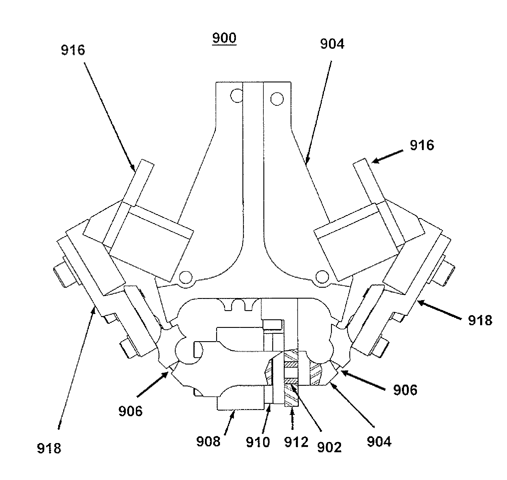
[0050]As is described above, the present invention approximates a negative spring constant. The negative spring constant is approximated with the partial closing of an air gap in a permanent magnet-iron magnetic circuit as shown in the different embodiments of FIGS. 5, 6, 7, 8 and 9.

[0051]FIGS. 5a to 5e each show without limitation an example of an embodiment for the two (2) magnet circuits 500 where the same reference numeral identifies the same element in all of the figures. Thus reference numerals 502 and 504 which appear in all of the figures identify a first ferromagnetic base and a permanent magnet respectively. Reference numeral 506 which appears only in FIG. 5c identifies a second ferromagnetic base.

[0052]FIG. 5a shows a single magnet configuration. FIG. 5b shows an extended single magnet configuration. FIG. 5c shows in a sectional view a closed loop single magnet configuration. FIG. 5d shows a double magnet configuration. FIG. 5e shows in a sectional view a single ring shap...


PUM

PropertyMeasurementUnit
restoring torqueaaaaaaaaaa
optical mechanismaaaaaaaaaa
magnetic fieldaaaaaaaaaa

Abstract

An optical scanning or positioning mechanism has a head on which optical components are mounted and an actuator coupled to the head to cause the head to move when the actuator is actuated. There are one or more sets of flexure bearings mounted in the mechanism. The flexure bearings have a restoring torque when moved from a rest position. The bearings are coupled to the head to allow the head to move when actuated by the actuator. One or more magnets are mounted in the mechanism in a location other than in the actuator to compensate for the flexure bearings restoring torque.

Description

[0001]1. Field of the Invention[0002]The present invention relates to opto-mechanical assemblies providing for translational or rotational movement or positioning of optical element(s) with respect to an axis governed by flexure bearings or blades or integral flexures (all of which are referred to hereinafter as “flexure bearings” solely for ease of description and not as a limitation on the scope of the present invention) and more particularly to the compensation of the restoring torque of the flexure bearings.[0003]2. Description of the Prior Art[0004]Flexure bearings employed for partial rotation about a pivot point have several advantages over other types of bearings. Flexure bearings have no backlash and hence ensure precise repeatable motion. Flexure bearings do not have friction and do not require lubrication. The operational life of flexure bearings can be indefinitely long when stresses in the flexure bearing blades are limited to below the endurance stress of the bearing m...

Claims


Application Information

Patent Timeline
Patent Type & Authority Applications(United States)
IPC IPC(8): G02B26/10H05K13/04
CPCG01J3/02G02B7/1828G01J3/06Y10T29/49002Y10T29/5313F16C11/12G01J3/0202G02B7/1821
Inventor DEMERS, MATHIEU J.LANDRY, JAMES T.BUIJS, HENRY L.
Owner ABB INC
Learn More