
Device for and a method of processing audio data

a technology of audio data and audio data, applied in the field of audio data processing devices, can solve the problems of inconvenient user switching channels, affecting the overall experience, and affecting the user's listening experience, so as to achieve convenient use for listeners

Active Publication Date: 2011-02-17
NXP BV
View PDF13 Cites 19 Cited by
  • Summary
  • Abstract
  • Description
  • Claims
  • Application Information

AI Technical Summary

Benefits of technology

[0020]According to an exemplary embodiment of the invention, a system may be provided which automatically detects that a user wears headphones or other audio reproduction units in an erroneous manner, i.e. that the user has attached a first audio reproduction unit (to be correctly attached to a left ear) to a right ear and has attached a second audio reproduction unit (to be attached correctly to the right ear) to the left ear. In the case of the reproduction of orientation-dependent or spatially-dependent audio data, such a left / right inversion may have a negative impact on the perception of the audio data. Hence, a self-acting detection system may be provided by an exemplary embodiment which may recognize the erroneous wearing of the headphones and may exchange the audio data to be reproduced by the two audio reproduction units upon detection of such an erroneous wearing mode. In other words, the first audio reproduction unit is then operated to reproduce right ear audio data and the second audio reproduction unit is then operated to reproduce left ear audio data. Thus, without requiring a user to perform a correction action and hence in a user-convenient manner, it may be ensured that even an unskilled user can safely enjoy orientation or position-dependent audio data in a simple and reliable manner.
[0025]Such an embodiment can be realized in a particularly simple and efficient manner using an Active Noise Reduction (ANR) system which may already have assigned to each loudspeaker a corresponding microphone. Although this microphone is predominantly used for another purpose in an Active Noise Reduction system (namely for detecting environmental noise to allow to correspondingly manipulate a played back audio signal to compensate for audible disturbation in an environment), these microphones can be used synergetically for detecting the signal which allows to determine the positions of the two audio reproduction unit and therefore to determine a possible left / right inversion.
[0026]In an ANR system implemented according to an exemplary embodiment, a noise-cancellation speaker may emit a sound wave with the same amplitude but with inverted phase to the original sound. The waves combine to form a new wave, in a process called interference, and effectively cancel each other out by phase cancellation. The resulting sound wave may be so faint as to be inaudible to human ears. The transducer emitting the cancellation signal may be located at the location where sound attenuation is wanted (for instance the user's ears). In an embodiment, the first audio reproduction unit and the second audio reproduction unit may be adapted for Active Noise Reduction. Active Noise Reduction (ANR) headsets may reduce the exposure to ambient noise by playing so-called “anti-noise” through headset loudspeakers. A basic principle is that the ambient noise is picked up by a microphone, filtered and phase-reversed with an ANR filter, and sent back to the loudspeaker. In case of a feed forward ANR, the microphone may be arranged outside the ear cup. In case of a feedback ANR, the microphone may be arranged inside the ear cup. The additional microphones used for Active Noise Reduction may be simultaneously and synergetically used as well for the detection of a possible left / right inversion.
[0027]However, other embodiments of the invention may be implemented in others than Active Noise Reduction system. Hence, the addition of separate microphones spatially located at the positions of the audio reproduction units is possible even without providing an ANR function.
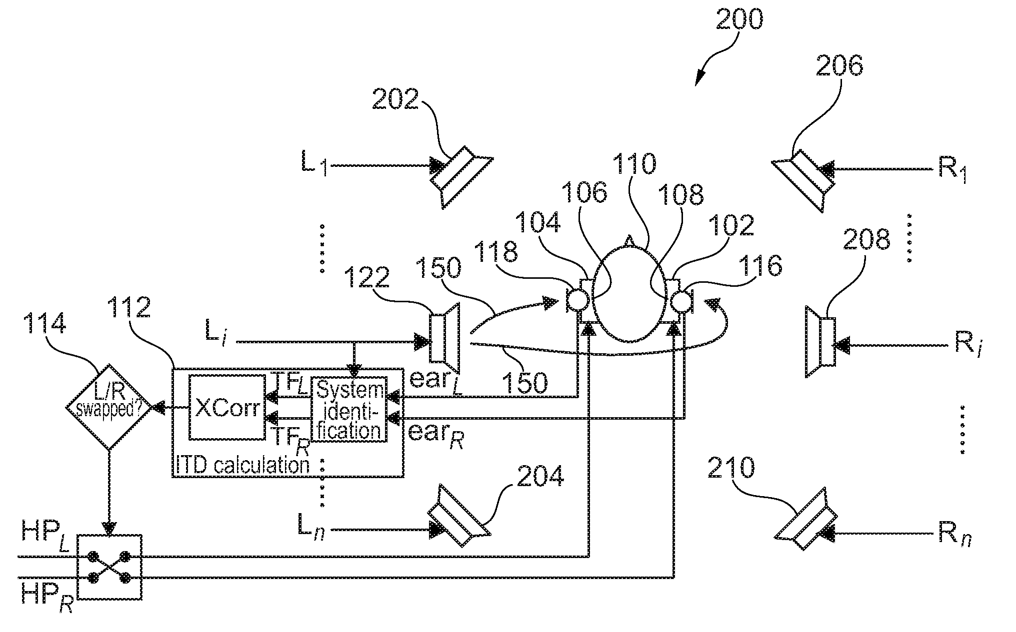
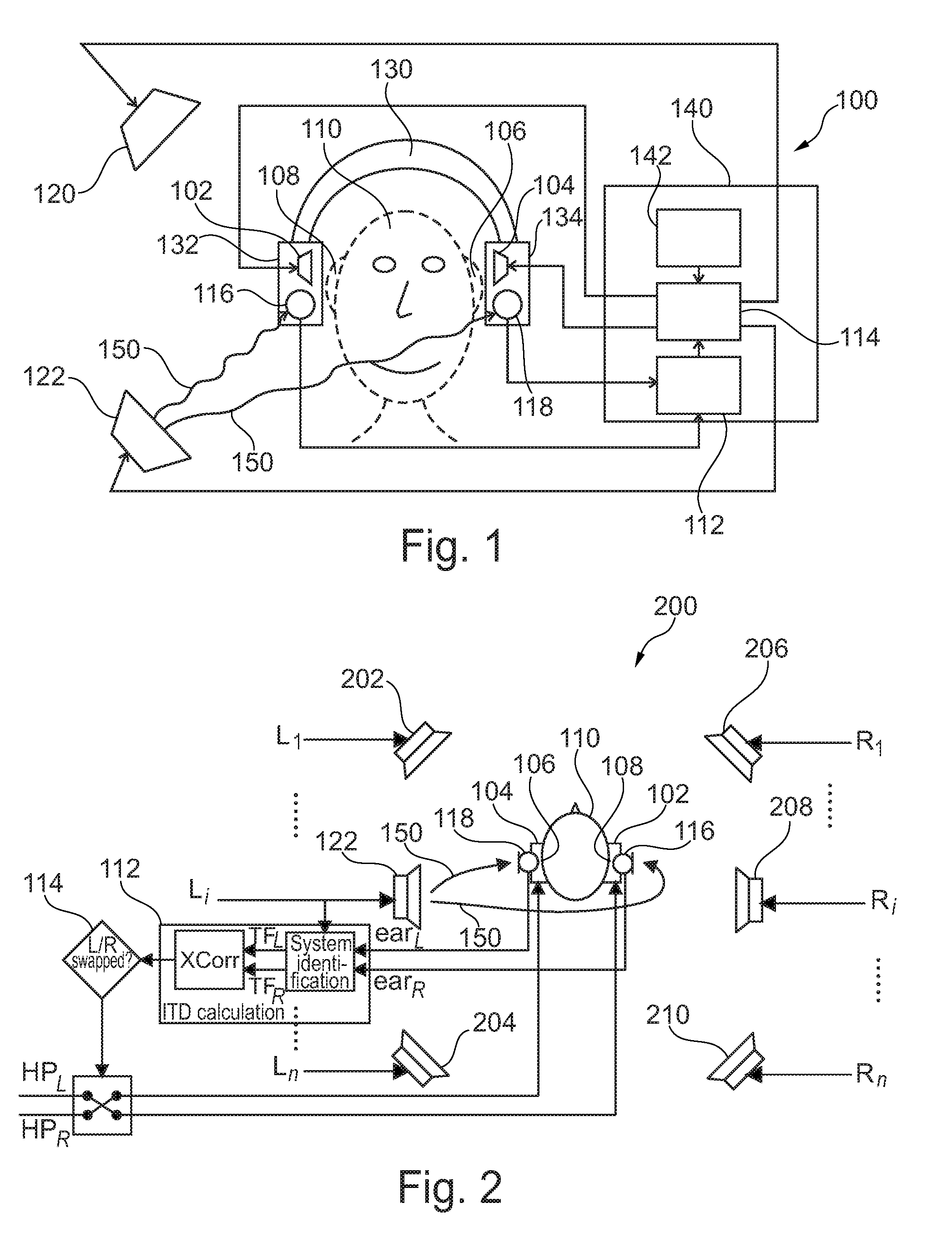
[0031]In an embodiment, the signal emission unit may comprise at least one further audio reproduction unit adapted for reproducing further audio data independently from the first audio reproduction unit and the second audio reproduction unit, wherein the reproduced further audio data may constitute the reference signal. Therefore, one or more further loudspeakers as further audio reproduction units may be arranged in an environment of the first and the second audio reproduction units (which may be represented by a headphone or the like) so that such further audio reproduction unit or units may serve for generating the reference signal, i.e. may function as the signal emission unit for emitting a reference signal. Therefore, the left / right inversion can be performed in a very simple manner without additional hardware requirements when one or more further loudspeakers are positioned anyway in an environment of the headphones forming the first and the second audio reproduction units.

Problems solved by technology

A left / right inversion may be not dramatic in case of music listening, but for instance in case of movie playback and augmented reality systems (such as auditory displays), a left / right inversion has a negative impact on the overall experience.
Although headphones may be marked with a “L” on the left earpiece and a “R” on the right earpiece, it is not convenient for the user to look for those indications each time the user has to put the headphones on.
Some conventions exist though, like cable plug on the left side for full-size headphones or shorter cable on the left side for in-ear headphones, but they are not generalized and do not prevent the user from swapping the channels inadvertently.

Method used


Image

  • Device for and a method of processing audio data
  • Device for and a method of processing audio data
  • Device for and a method of processing audio data

Examples


Embodiment Construction

[0042]The illustration in the drawing is schematically. In different drawings, similar or identical elements are provided with the same reference signs.

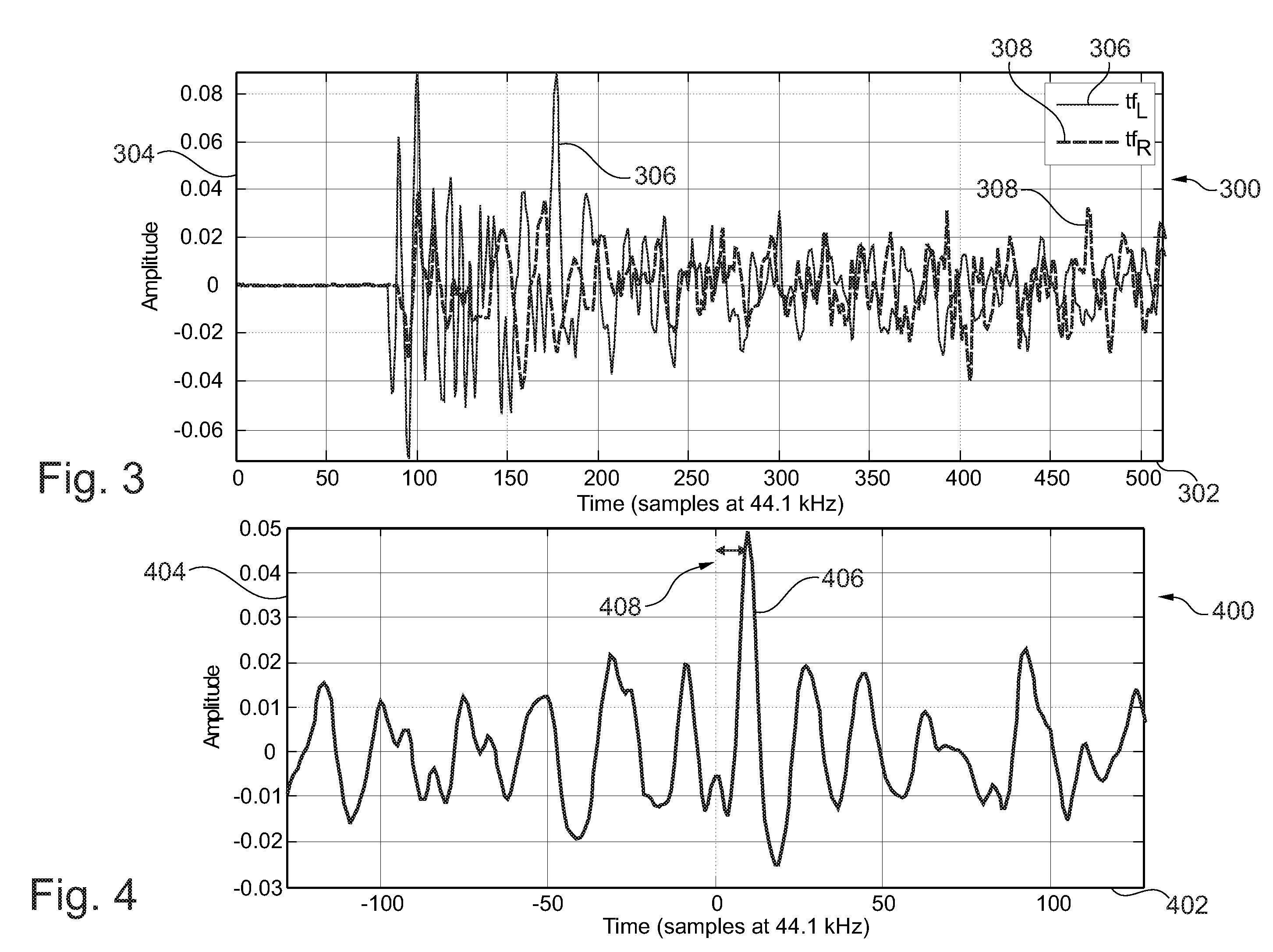
[0043]According to an exemplary embodiment of the invention, an automatic left / right headphone inversion detection, for instance for rear-seat entertainment headphones, may be provided. An embodiment provides a system for automatically detecting left / right inversion for instance for Active Noise Reduction headphones used for in-car rear-seat entertainment. Such a system may exploit the fact that microphones on a headset (one on each side of the listener's head) are surrounded by loudspeakers from the car audio installation that are playing known signals. It may make it possible to monitor the acoustical paths between one (or more) of those loudspeakers and the two headset microphones. For each loudspeaker, the least delayed microphone should be the one on the same side as the loudspeaker. If not, it indicates that the headphone is sw...


PUM


Abstract

A device (100) for processing audio data, wherein the device (100) comprises a first audio reproduction unit (102) adapted for reproducing a first part of the audio data and adapted to be attached to a left ear (106) of a user (110), a second audio reproduction unit (104) adapted for reproducing a second part of the audio data and adapted to be attached to a right ear (108) of the user (110), a detection unit (112) adapted for detecting a left / right inversion of the first audio reproduction unit (102) and the second audio reproduction unit (104), and a control unit (114) adapted for controlling the first audio reproduction unit (102) for reproducing the second part of the audio data and for controlling the second audio reproduction unit (104) for reproducing the first part of the audio data upon detecting the left / right inversion.

Description

[0001]This application claims the priority under 35 U.S.C. §119 of European patent application no. 09168012.4, filed on Aug. 17, 2010, the contents of which are incorporated by reference herein.FIELD OF THE INVENTION[0002]The invention relates to a device for processing audio data.[0003]Beyond this, the invention relates to a method of processing audio data.[0004]Moreover, the invention relates to a program element.[0005]Furthermore, the invention relates to a computer-readable medium.BACKGROUND OF THE INVENTION[0006]Headphone listening is getting more and more popular due to the penetration of portable audio players. Even mobile phones nowadays also allow music playback on headphones. Headphones are also increasingly used in rear-seat entertainment (RSE) systems: this allows people sitting at the back of the car to listen to music or watch DVDs without being disturbed by the music being played on the main car audio installation, and without disturbing the front passengers.[0007]Ano...

Claims


Application Information

Patent Timeline
Patent Type & Authority Applications(United States)
IPC IPC(8): H04R5/00
CPCH04R5/04H04R25/552H04R2201/109H04R2420/01H04R25/43H04R2460/01H04S1/005H04S7/304H04R2420/03
Inventor MACOURS, CHRISTOPHE MARC
Owner NXP BV
Learn More