
System and Method for Coating a Medical Device

a technology for medical devices and coatings, applied in the field of coating a medical device, can solve the problems of pooling or webbing of the coating substance, difficult application of uniform coatings with good adhesion to the substrate, and inability to meet the requirements of small and intricate medical devices. uniform coating thickness and distribution

Inactive Publication Date: 2011-02-17
ABBOTT CARDIOVASCULAR
View PDF21 Cites 41 Cited by
  • Summary
  • Abstract
  • Description
  • Claims
  • Application Information

AI Technical Summary

Benefits of technology

"The present invention is about a system and method for coating medical devices. The system includes an enclosure with two apertures, a coating dispenser, a gas dispenser, and two support devices. The system can move the medical device between the spray area and the drying area while applying the coating. The method involves moving the first medical device out of the spray area to the drying area, discharging gas onto the first medical device in the drying area, and applying a coating on the second medical device in the spray area while discharging the gas onto the first medical device in the drying area. The technical effects of the invention include improved coating efficiency and reduced risk of damage to the medical device during coating."

Problems solved by technology

Problems with PTCA include formation of intimal flaps or torn arterial linings, both of which can create another occlusion in the lumen of the coronary artery.
Moreover, thrombosis and restenosis may occur several months after the procedure and create a need for additional angioplasty or a surgical bypass operation.
The application of a uniform coating with good adhesion to a substrate can be difficult for small and intricate medical devices, such as certain stents for coronary and peripheral arteries.
Coating of the thin network of struts often leads to pooling or webbing of the coating substance where struts meet, non-uniform coating thickness and distribution, delamination, contamination.
Many spray coating systems are inefficient and produce a high incidence of coating defects due in part to insufficient control of the spray and dry environment.
Thus, it can be difficult to keep track of coating cycles and the types or batches of coating substances for each cycle.
To ensure accurate tracking, many systems and methods involve a one-piece flow manufacturing model wherein a spray coating machine processes one stent at a time, which can be inefficient and time consuming because of the time require for drying between coats and because of the need for multiple coats on each stent.
A disadvantage of this approach is that it deviates from the one-piece flow manufacturing scheme that controls stent identity in a highly reliable way and, thus, may allow stents to become mixed up from time to time due to loss of tracking identity.
Loss of tracking identity causes a stent, or even an entire production lot of stents, to be scrapped to waste.
Another difficulty in producing drug-coated medical devices, such as drug eluting stents, is that the drugs, solvents, and other substances used in the manufacturing process can be dangerous to the health of human operators of manufacturing equipment.

Method used


Image

  • System and Method for Coating a Medical Device
  • System and Method for Coating a Medical Device
  • System and Method for Coating a Medical Device

Examples


Embodiment Construction

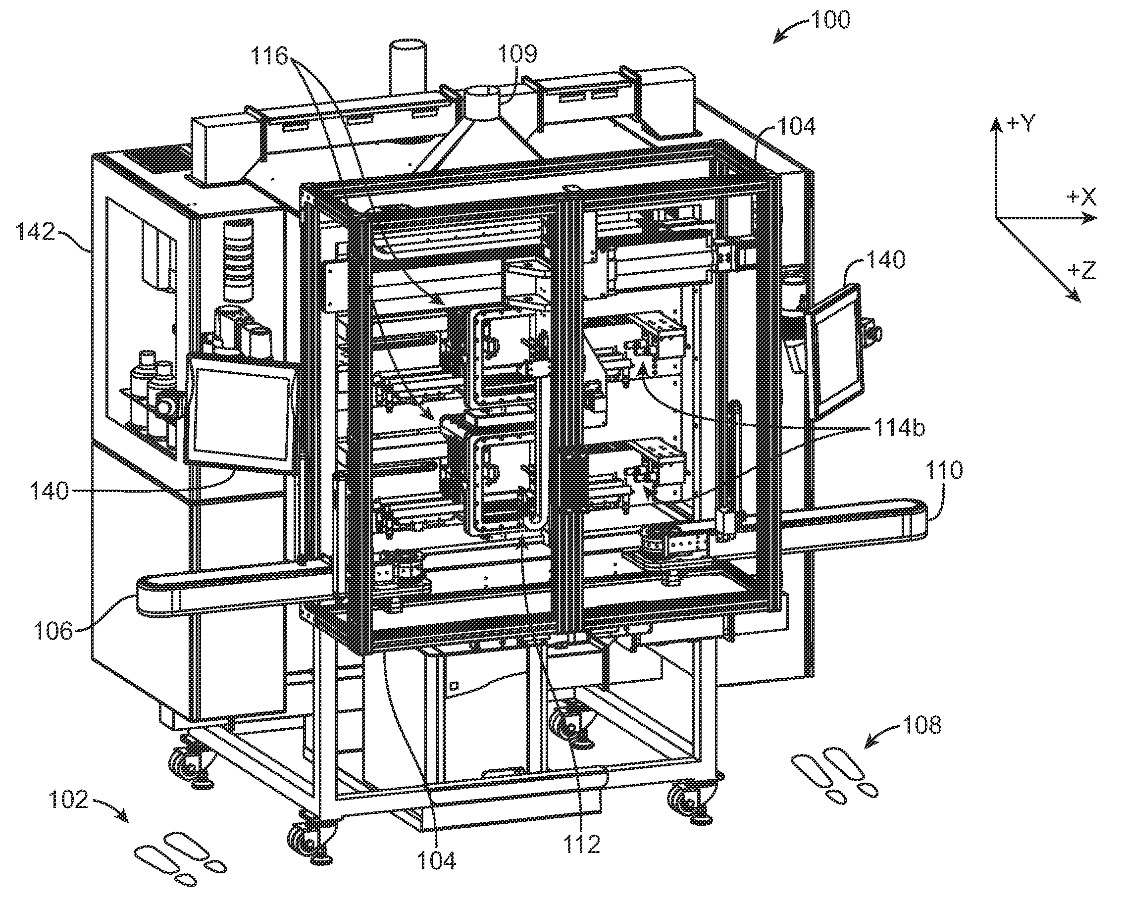
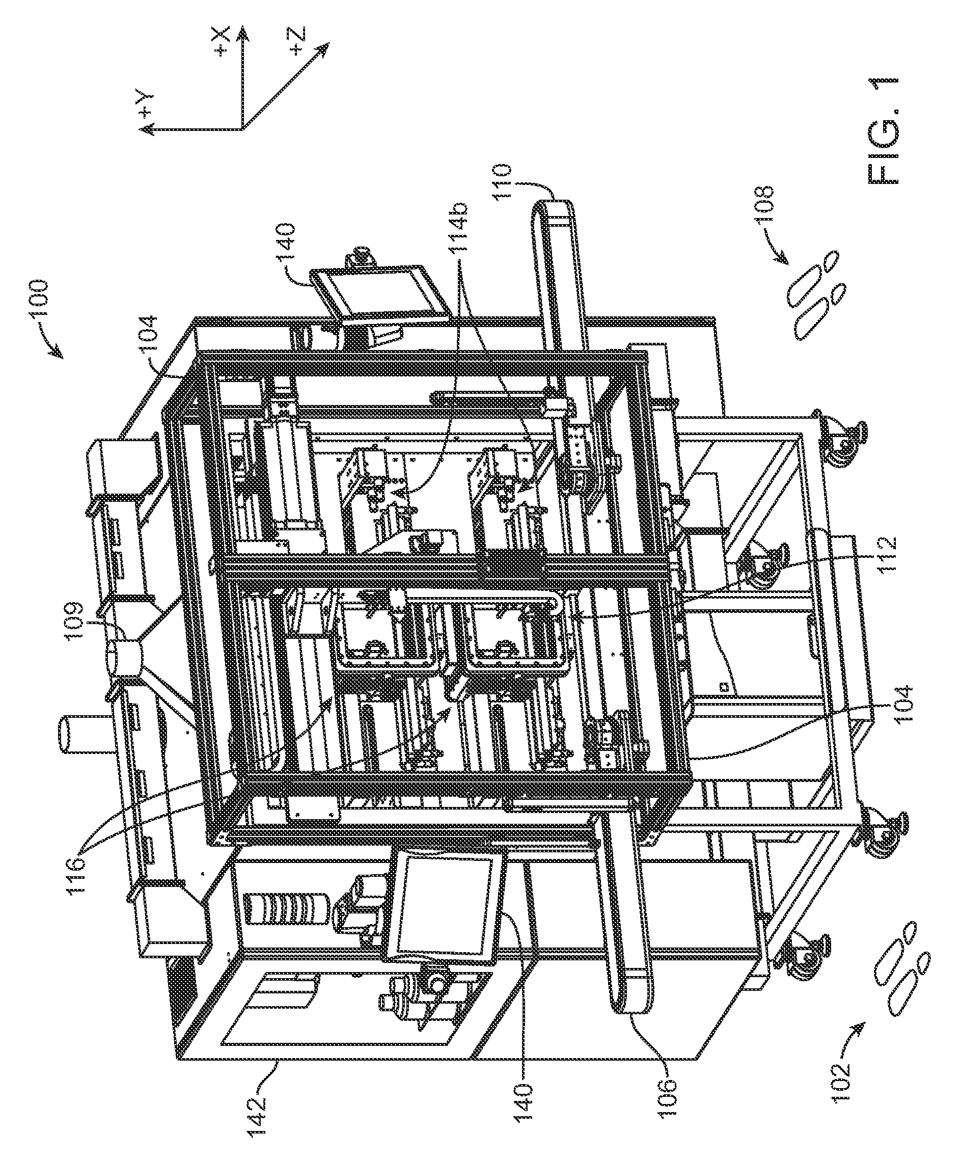
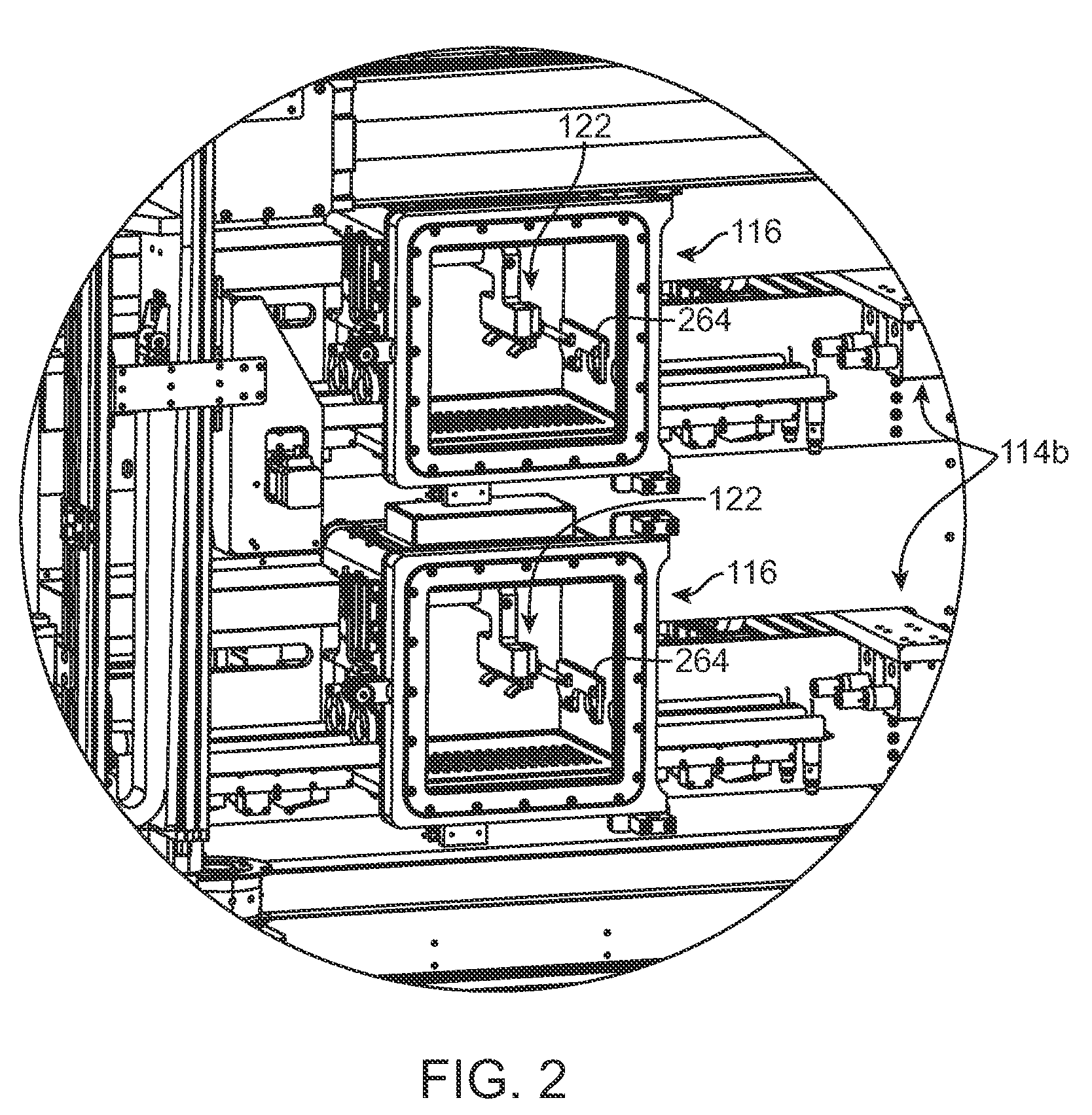
[0038]Referring now in more detail to the exemplary drawings for purposes of illustrating embodiments of the invention, wherein like reference numerals designate corresponding or like elements among the several views, there is shown in FIG. 1 a stent coating system 100 providing a controlled manufacturing environment for transporting, spraying, and drying of a medical device.

[0039]In use, a person stands at position 102 outside of a transparent shielded enclosure 104 and places stents to be coated on an inbound conveyor assembly 106. Another person stands at position 108 outside of the shielded enclosure 104 and removes coated stents from an outbound conveyor assembly 110. The stents are not handled directly. Each stent is individually carried on separate carrying devices, referred to herein as a “mandrel,” and may be moved independently of each other from point to point during the coating process via direct manipulation of the mandrel. The mandrel is configured to retain the stent ...


PUM

PropertyMeasurementUnit
sizeaaaaaaaaaa
angleaaaaaaaaaa
angleaaaaaaaaaa

Abstract

A system and method allows for processing of two groups of medical devices, both groups being alternatingly spray coated within the same enclosure. The two groups repeatedly move back and forth between a spray area and a drying area which is isolated from the spray area. One group moves into the spray area as the other group moves out and into the drying area. Thereafter, the group in the spray area moves out and into the drying area and the other group moves back into the spraying area for a second coating. The alternating process may be repeated any number of times. The spray area may be located inside a sealed spray isolator enclosure and surrounded by gas discharge nozzles.

Description

FIELD OF THE INVENTION[0001]Briefly and in general terms, the present invention generally relates to coating a medical device, more specifically, to a system and method for coating a stent.BACKGROUND OF THE INVENTION[0002]In percutaneous transluminal coronary angioplasty (PTCA), a balloon catheter is inserted through a brachial or femoral artery, positioned across a coronary artery occlusion, and inflated to compress against atherosclerotic plaque to open, by remodeling, the lumen of the coronary artery. The balloon is then deflated and withdrawn. Problems with PTCA include formation of intimal flaps or torn arterial linings, both of which can create another occlusion in the lumen of the coronary artery. Moreover, thrombosis and restenosis may occur several months after the procedure and create a need for additional angioplasty or a surgical bypass operation. Stents are used to address these issues. Stents are small, intricate, implantable medical devices and are generally left impl...

Claims


Application Information

Patent Timeline
Patent Type & Authority Applications(United States)
IPC IPC(8): B05D3/04B05C5/00B05C13/02B05C11/00
CPCA61F2/82F26B9/06A61L2420/02B05B13/0221B05B13/0228B05B13/041B05B15/1207B05B15/1222B05B15/1288B05D1/002B05D1/02B05D3/0413B05D3/0493B05D7/584A61F2310/00389B05B16/20B05B16/60B05B16/90
Inventor PAPP, JOHN E.GILLICK, MATTHEW J.STALKER, KENT C. B.
Owner ABBOTT CARDIOVASCULAR
Learn More