Organic light emitting diode touch display

a light-emitting diode and touch display technology, which is applied in the direction of static indicating devices, cathode-ray/electron beam tube circuit elements, instruments, etc., can solve the problems of increased total thickness of the panel, weak backlight light, and reduced light transmittance of the oled panel

Active Publication Date: 2011-02-24
AU OPTRONICS CORP
View PDF13 Cites 65 Cited by
  • Summary
  • Abstract
  • Description
  • Claims
  • Application Information

AI Technical Summary

Problems solved by technology

However, components, such as resistance devices and capacity devices, are placed on a panel directly, so it results in a decrease in light transmittance of OLED panels and an increase in total thickness of the panel.
However, light produced by the backlight is quite weak after being reflected, so under conditions of dim environment the signals that are sensed by the light sensor are usually weak, and signal recognition is less accurate as well.
Moreover, if images, surrounding the zone that needs touching being at lower gray level (e.g., black), are intended to be dragged, it is easier to result in being unable to sense because of lack of light quantity of pixels.

Method used


Image

  • Organic light emitting diode touch display
  • Organic light emitting diode touch display
  • Organic light emitting diode touch display

Examples


Embodiment Construction

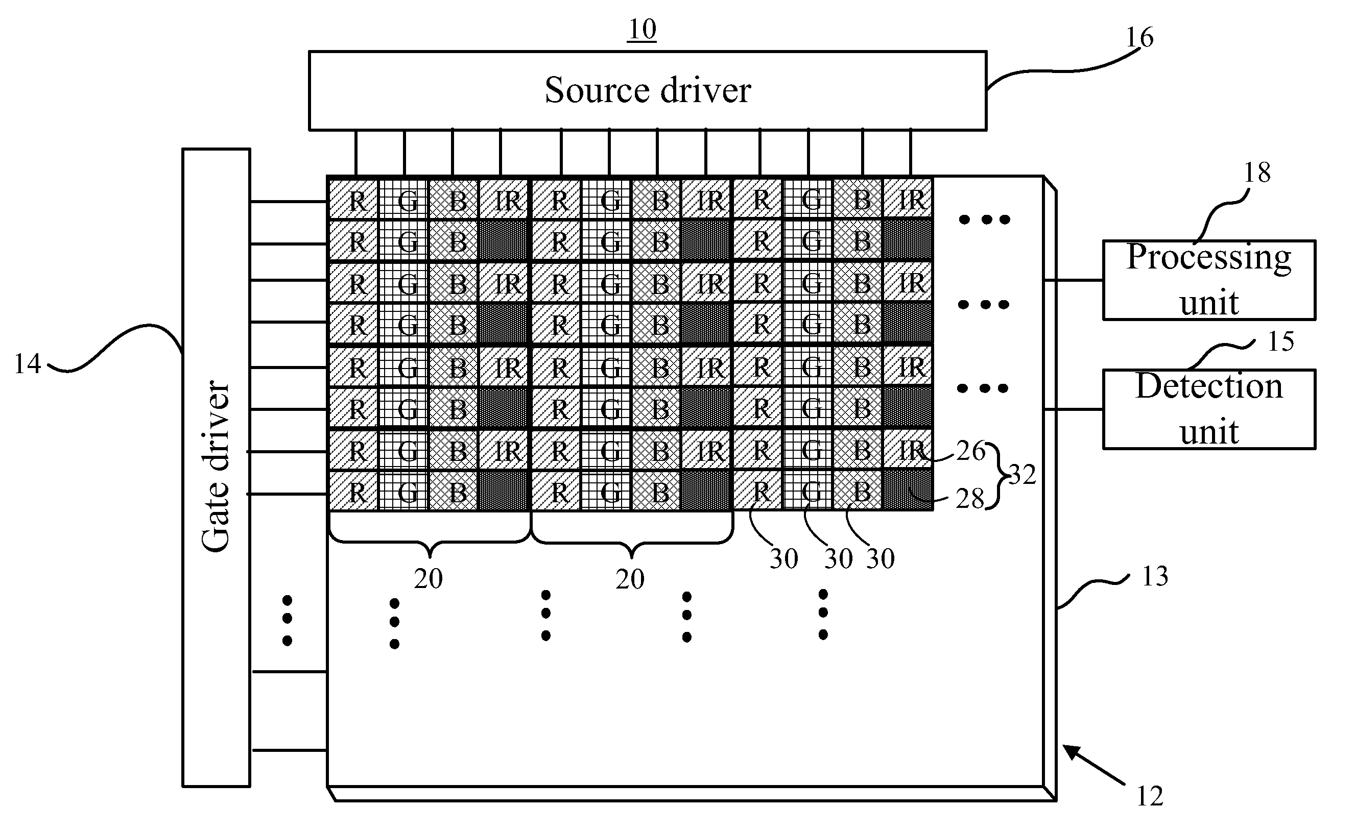
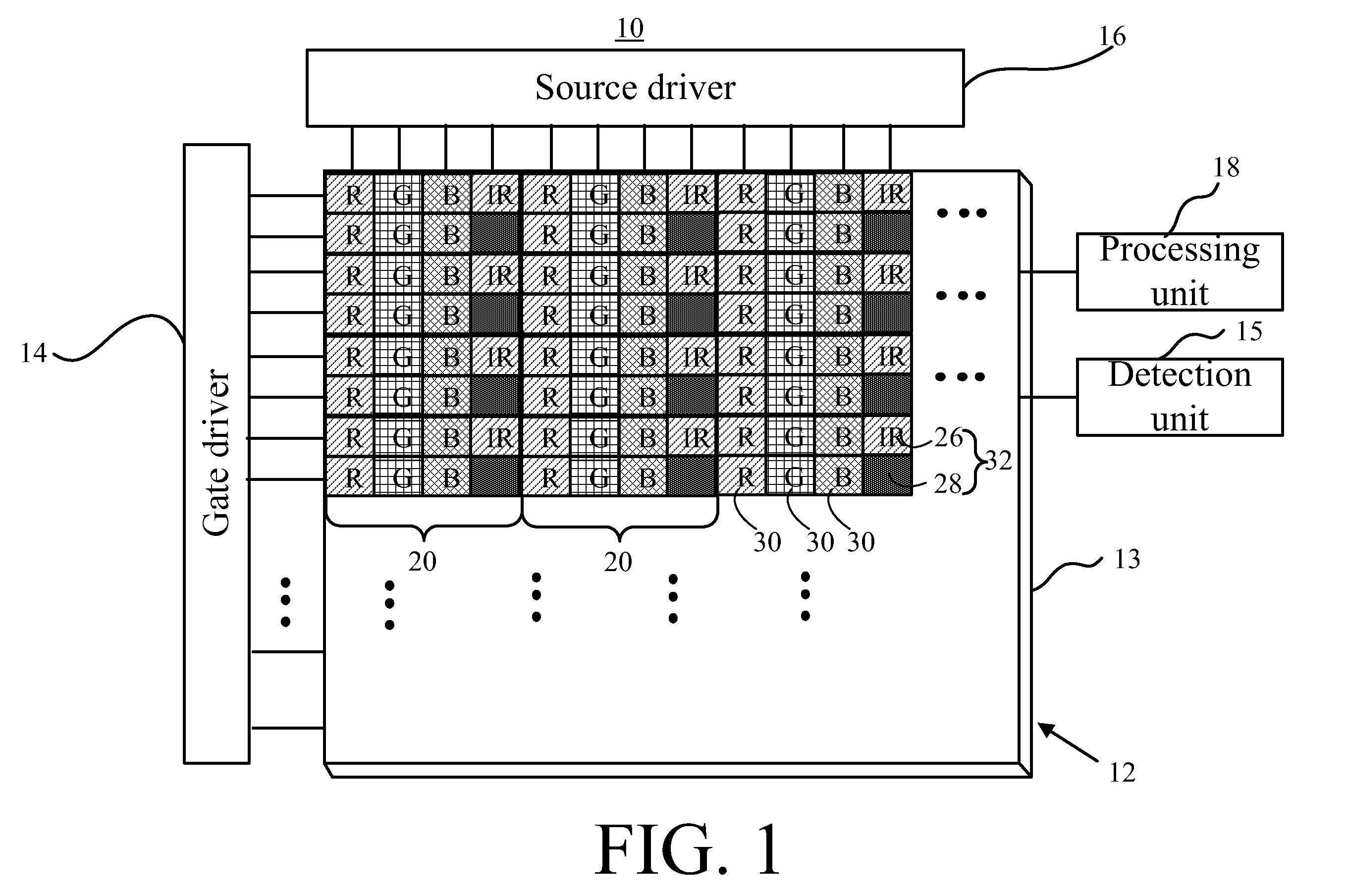
[0028]Referring to FIG. 1 showing a diagram of an OLED display 10 according to a preferred embodiment of the present invention, the OLED display 10 comprises an OLED panel 12, a gate driver 14, a source driver 16, a processing unit 18, and a detection unit 15. The OLED panel 12 comprises a substrate 13 having a display region formed by a plurality of pixel units 30, which represents the three primary colors—red, green, and blue (RGB)—respectively, and a plurality of infrared (IR) units 32. The IR unit 32 comprises an infrared emitting region 26 and an infrared sensitive region 28. The infrared emitting region 26 is employed to emit infrared rays, and the infrared sensitive region 28 is utilized to sense the infrared rays reflected from an object. As shown in FIG. 1, at least six pixel units 30 are arranged with one infrared unit 32.

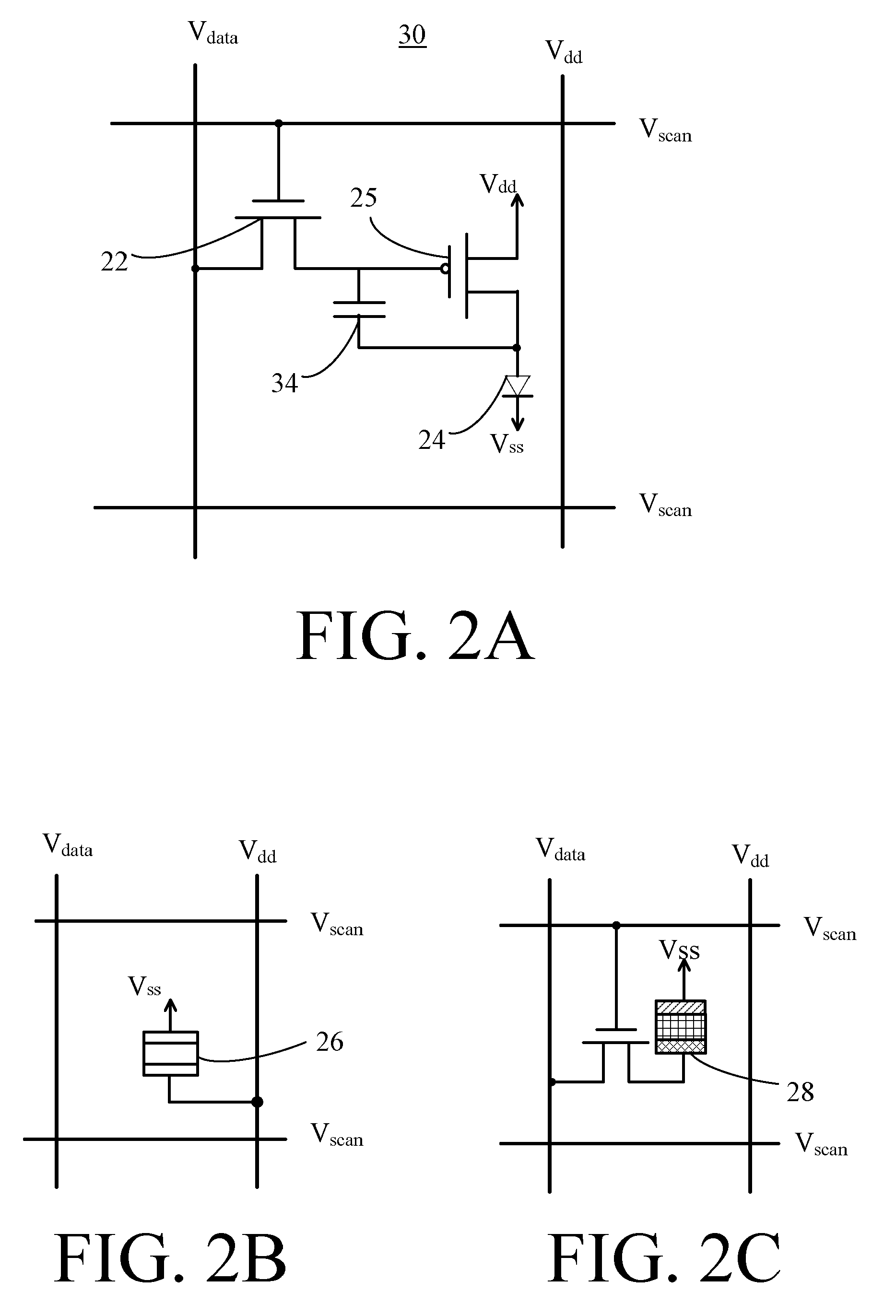
[0029]Referring to FIG. 2A, 2B, and 2C, FIG. 2A illustrates an equivalent circuit diagram of the pixel unit 30 in FIG. 1 according to a first embodiment ...


PUM


Abstract

An OLED display is proposed. The OLED display includes a gate driver for generating a scanning signal, a source driver for generating a data signal, and a plurality of cells arranged in an array. Each cell includes a first transistor for delivering the data signal when receiving the scanning signal, a second transistor for generating a driving current based on a voltage difference between a first supply voltage signal and the data signal, a storage capacitor coupled between the first transistor and an output end of the driving circuit, for storing the data signal, an organic light emitting diode for generating light based on the driving current, an infrared emitting layer for producing infrared ray, and an infrared sensitive layer for sensing the infrared ray reflected by an object.

Description

BACKGROUND OF THE INVENTION[0001]1. Claim of Priority[0002]The present application claims priority to Taiwanese Patent Application No. 098122480 filed on Jul. 2, 2009 and Taiwanese Patent Application No. 099121792 filed on Jul. 2, 2010.[0003]2. Field of the Invention[0004]The present invention relates to an organic light emitting diode (OLED) display, and more particularly, to an organic light emitting diode touch display.[0005]3. Description of the Related Art[0006]With a rapid development of monitor types, novel and colorful monitors with high resolution, e.g., organic light emitting diode (OLED) displays, are indispensable components used in various electronic products such as monitors for notebook computers, personal digital assistants (PDAs), digital cameras, and projectors. The demand for the novelty and colorful monitors has increased tremendously.[0007]Luminous intensity of organic light emitting diode displays is determined by forward bias current of a light emitting diode ...

Claims


Application Information

Patent Timeline
Patent Type & Authority Applications(United States)
IPC IPC(8): G06F3/042H01J7/44
CPCG06F3/042G06F3/0412G09G3/32G09G3/3233G09G2300/0819G09G2360/14G09G2360/142H10K59/40
Inventor HUANG, JUNG-YENCHO, AN-THUNGHSU, SHIH-FENGHUANG, WEI-PANGPENG, CHIA-TIEN
Owner AU OPTRONICS CORP
Why Eureka
Try Eureka