
Resolution-Enhanced Luminescence Microscopy

a luminescence microscopy and luminescence enhancement technology, applied in the field of high spatial resolution luminescence microscopy, can solve the problems of inability to use the current method for thick samples, disadvantages, and unnecessary radiation of samples in regions

Inactive Publication Date: 2011-02-24
CARL ZEISS MICROSCOPY GMBH
View PDF6 Cites 10 Cited by
  • Summary
  • Abstract
  • Description
  • Claims
  • Application Information

AI Technical Summary

Benefits of technology

[0018]The invention is based on the task of refining a method or a device for PAL microscopy so that faster image production is achieved.

Problems solved by technology

For this method it is to be considered disadvantageous that the sample is charged with radiation unnecessarily in regions outside of the detected focus, because the necessary structured illumination penetrates the entire sample volume.
Incidentally, this method could not be used currently for thick samples, because fluorescence excited outside of the focal area is led as a background signal onto the detector and thus the dynamic region of the detected radiation is drastically reduced.
This has the result that large quantities of data are processed and the measurement accordingly takes a long time.
On the other hand, the imaging of a thick sample by an image stack requires an especially large number of images.
One could easily imagine that, at four hours for each total image, the recording of an image stack made from total images requires an enormous amount of time.

Method used


Image

  • Resolution-Enhanced Luminescence Microscopy
  • Resolution-Enhanced Luminescence Microscopy
  • Resolution-Enhanced Luminescence Microscopy

Examples


Embodiment Construction

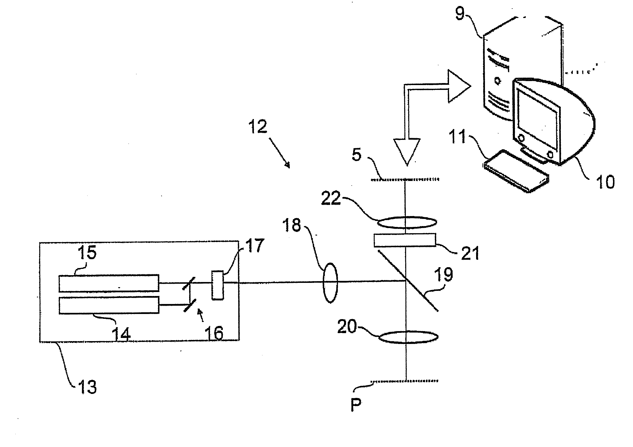
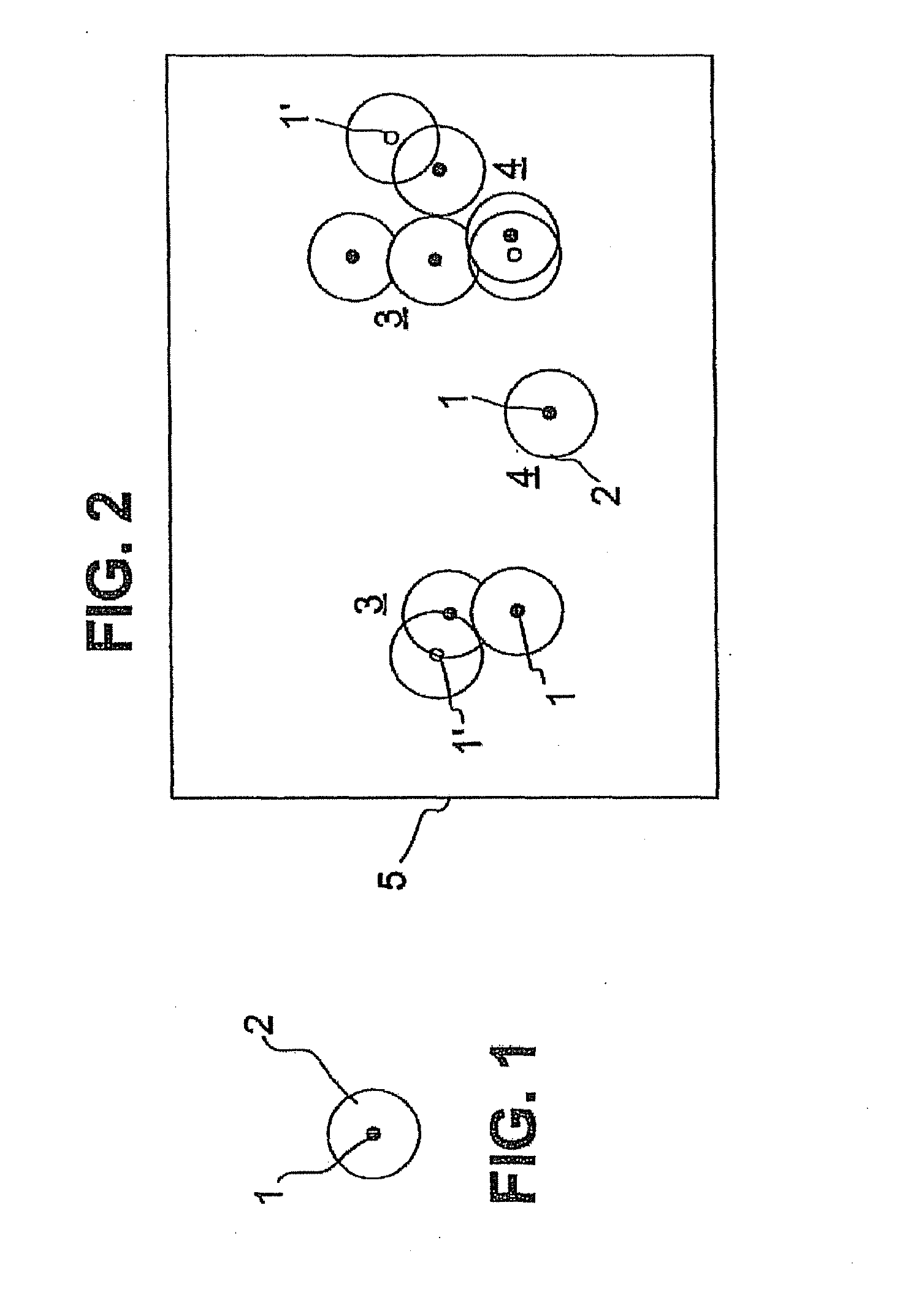
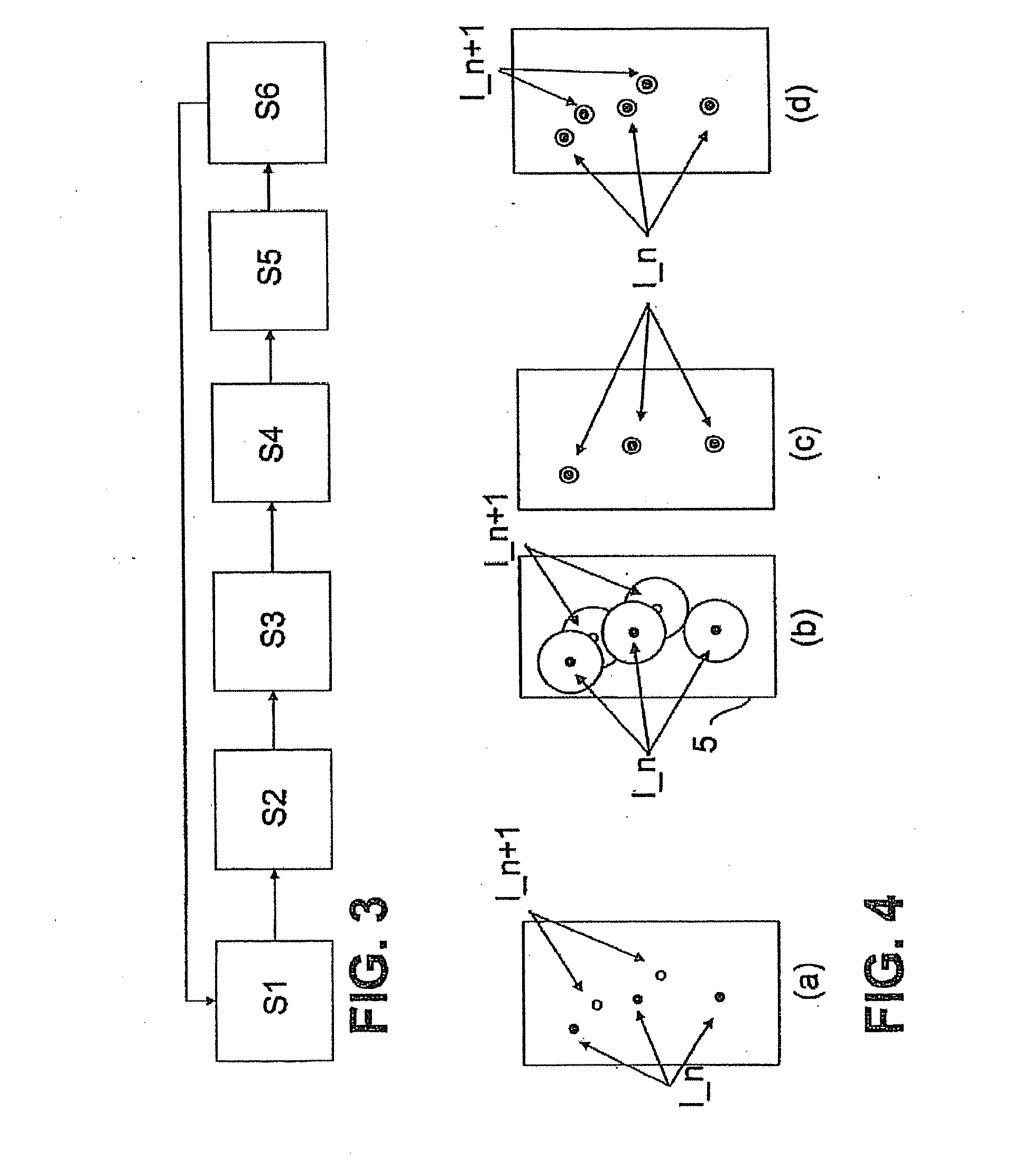
[0051]FIG. 1 shows schematically a marking molecule 1 that was excited for fluorescence. Naturally, the fluorescence detection requires a plurality of excitations, because each excitation delivers exactly one fluorescent photon and the radiation detection requires an integration of many photons. The fluorescent radiation emitted by the marking molecule 1 can be detected in a microscope based on physical principles only at a limited optical resolution. Even if the microscope reaches the diffraction limit of the optical resolution, the photons of the fluorescent marking molecule 1 are still scattered in a diffraction-limited way and thus detected in a diffraction slice 2. The microscope thus reproduces, in principle, instead of the geometric extent of the marking molecule 1, which is designated schematically as a black circle in FIG. 1, a larger object that is shown in FIG. 1 by the diffraction slice 2. The size of the diffraction slice 2 depends on the quality of the microscopy devic...


PUM


Abstract

Described is a method for the high spatial resolution luminescence microscopy of a sample which is marked with marking molecules which can be activated by way of a switch-over signal such that only then can they be stimulated to emit luminescent radiation, wherein the method has the following steps a) introducing the switch-over signal onto the sample such that only a partial amount of the marking molecules present in the sample are activated, wherein, partial regions exist in the sample, in which partial regions only exactly one molecule, which is activated by the switch-over signal, is located inside a volume which is delimited by a diffraction-limited maximum resolution of a detection of luminescent radiation, b) stimulating the activated molecules to emit luminescent radiation, c) detecting the luminescent radiation with diffraction-limited resolution and d) generating image data from the luminescent radiation recorded in step c), wherein the marking molecules, which emit the geometric locations of the luminescent radiation, indicate with a spatial resolution which is increased to above the diffraction limit, wherein e) the detection of the luminescent radiation in step c) or the generation of the image data in step d) comprises a non-linear increase, which prefers higher intensities, of recorded luminescent radiation in order to enhance the spatial resolution to above the diffraction-limited resolution.

Description

[0001]The present application is a U.S. National Stage application of International PCT Application No. PCT / EP2009 / 003036 filed on Apr. 25, 2009 which claims priority benefit of German Application No. DE 10 2008 021 641.0 filed on Apr. 30, 2008, the contents of each are incorporated by reference in their entirety.FIELD OF THE INVENTION[0002]The invention relates to a method for the high spatial resolution luminescence microscopy of a sample that is marked with marking molecules that can be activated with a switch-over signal, so that only then can they be excited for the emission of defined luminescent radiation, wherein the method has the following steps:[0003]a) introduction of the switch-over signal to the sample such that only a subset of the marking molecules present in the sample is activated, wherein, in the sample, subareas exist in which activated molecules have a distance to the activated marking molecules most closely adjacent to these activated molecules, wherein this di...

Claims


Application Information

Patent Timeline
IPC IPC(8): H04N7/18
CPCG01N21/6428G01N21/6458G02B27/58G02B21/367G02B21/16
Inventor WOLLESCHENSKY, RALF
Owner CARL ZEISS MICROSCOPY GMBH
Learn More