
Systems and methods for providing a flushable catheter assembly

a technology of a catheter and a flushing device, which is applied in the field of infusion devices to achieve the effect of preventing the buildup of positive pressur

Active Publication Date: 2011-02-24
BECTON DICKINSON & CO
View PDF68 Cites 201 Cited by
  • Summary
  • Abstract
  • Description
  • Claims
  • Application Information

AI Technical Summary

Benefits of technology

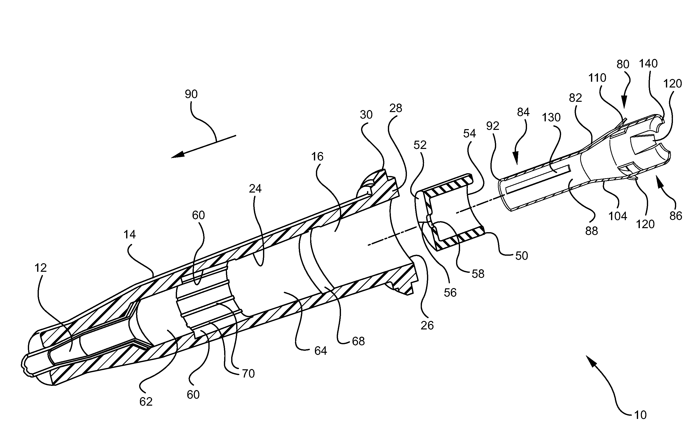
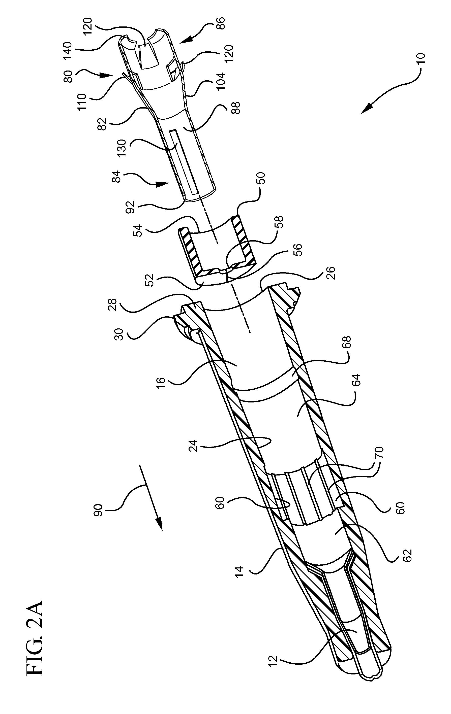
[0007]In some embodiments of the present invention, a septum is positioned within a lumen of the catheter assembly to prevent or limit flow of a fluid through the catheter adapter. The septum generally includes a flexible or semi-flexible material that is compatible with exposure to blood, medicaments, and other fluids commonly encountered during infusion procedures. In some embodiments, a groove is provided on an inner surface of the catheter adapter, wherein the septum is seated within the groove. As such, the position of the septum within the catheter adapter is maintained.
[0008]A closed or partially closed pathway, such as a slit or small hole is further provided in a barrier surface of the septum. The pathway permits fluid to bypass the septum and flow though the catheter adapter. In some embodiments, the pathway is a slit that is closed prior to being opened or activated by a probe or septum activator positioned within the lumen of the catheter adapter. Prior to being opened or activated, the slit prevents passage of fluid through the catheter adapter. Thus, in some embodiments a plurality of air vent channels are interposed between the septum and the groove to permit air flow through the catheter adapter prior to the slit being opened. The air vents prevent buildup of positive pressure within the catheter adapter thereby permitting flashback of blood into the catheter and a forward chamber of the catheter adapter.

Problems solved by technology

A common, yet undesirable practice is to permit blood to temporarily and freely flow from the catheter adapter while the clinician locates and couples the IV tubing to the catheter adapter.

Method used


Image

  • Systems and methods for providing a flushable catheter assembly
  • Systems and methods for providing a flushable catheter assembly
  • Systems and methods for providing a flushable catheter assembly

Examples


Embodiment Construction

[0021]The presently preferred embodiment of the present invention will be best understood by reference to the drawings, wherein like reference numbers indicate identical or functionally similar elements. It will be readily understood that the components of the present invention, as generally described and illustrated in the figures herein, could be arranged and designed in a wide variety of different configurations. Thus, the following more detailed description, as represented in the figures, is not intended to limit the scope of the invention as claimed, but is merely representative of presently preferred embodiments of the invention.

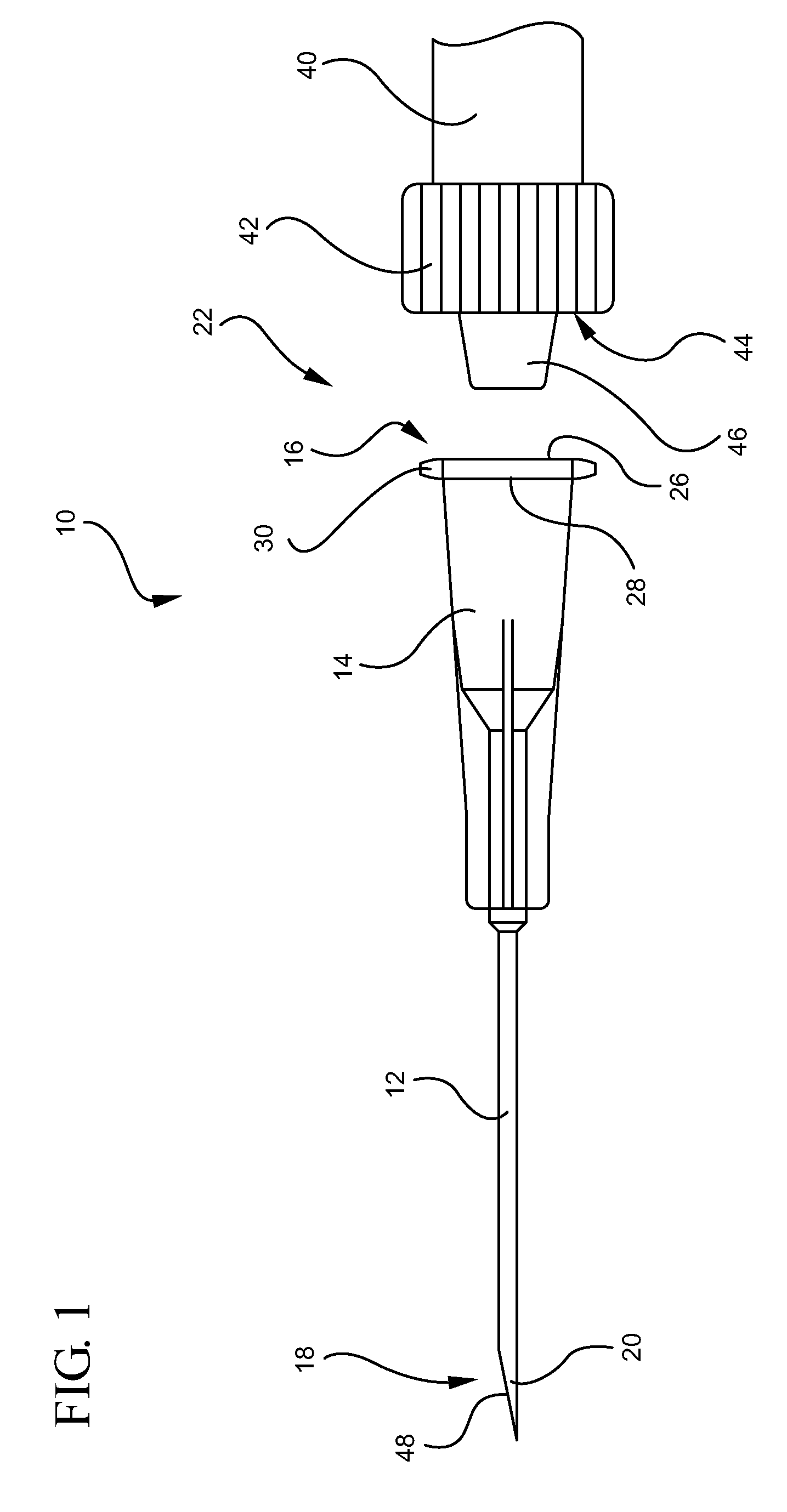
[0022]Referring now to FIG. 1, a catheter assembly 10 is illustrated. The catheter assembly 10 generally includes a catheter 12 coupled to a distal end 32 of a catheter adapter 14. The catheter 12 and the catheter adapter 14 are integrally coupled such that an internal lumen 16 of the catheter adapter 14 is in fluid communication with a lumen 18 of the...


PUM


Abstract

A flushable catheter assembly having features to enable selective activation of fluid flow through the catheter assembly is disclosed herein. A septum is placed within the catheter adapter of the catheter assembly and includes a pathway that is closed prior to being biased open via a septum activator also positioned within the catheter adapter. A plurality of air vent channels is interposed between the septum and the inner surface of the catheter adapter to permit “flashback” of blood during insertion of the catheter into a patient. The septum activator is advanced through the pathway of the septum as a coupler is attached to a proximal opening of the catheter adapter.

Description

BACKGROUND OF THE INVENTION[0001]The current invention relates to infusion devices, specifically to peripheral intravenous (IV) catheters. In particular, the invention relates to a flushable peripheral IV catheter assembly having features to enable selective activation of fluid flow through the catheter assembly.[0002]Catheters are commonly used for a variety of infusion therapies. For example, catheters are used for infusing fluids, such as normal saline solution, various medicaments, and total parenteral nutrition, into a patient, withdrawing blood from a patient, or monitoring various parameters of the patient's vascular system.[0003]Catheters and / or needles are typically coupled to a catheter adapter to enable attachment of IV tubing to the catheter. Thus, following placement of the catheter or needle into the vasculature of a patient, the catheter adapter is coupled to a fluid source via a section of IV tubing. In order to verify proper placement of the needle and / or catheter i...

Claims


Application Information

Patent Timeline
IPC IPC(8): A61M25/00B05D7/00
CPCA61M25/00A61M39/0693A61M2039/062A61M2039/066A61M2039/064A61M2039/0653A61M2039/0626
Inventor STOUT, MARTY L.ISAACSON, S. RAYSPINTI, MARKMCKINNON, AUSTIN JASON
Owner BECTON DICKINSON & CO
Learn More