Implant release mechanism

a release mechanism and implant technology, applied in the direction of catheters, stents, other medical devices, etc., can solve the problems of complex release and retrieval of implants, special design problems, and inability to use in conjunction with guide wires

Active Publication Date: 2011-02-24
COOK MEDICAL TECH LLC
View PDF12 Cites 13 Cited by
  • Summary
  • Abstract
  • Description
  • Claims
  • Application Information

AI Technical Summary

Benefits of technology

[0009]In a preferred embodiment, the releasable coupling member is operable to reattach a released implant to a delivery device. This enables a surgeon or clinician to adjust the position of an implant during deployment to ensure that it is correctly replaced. Furthermore, the mechanism can be used to remove an implant from a patient where the implant is intended to be only temporary. The releasable coupling member may be arranged to attach an implant distally of a catheter part of a deployment device.
[0010]Preferably, the coupling member, the blocking member and a guide wire together substantially fill a lumen of an implant at least at an implant-coupling portion. In this way, release of a coupling member from an implant is only possible once the blocking member has been moved.

Problems solved by technology

However, accommodation of a guide wire presents special design problems for other components of an implant delivery system.
One problem with prior art release mechanisms is that they cannot be used in conjunction with a guide wire.
Another problem is that known mechanisms for release and retrieval of an implant are complex and thus take up a lot of space within an introducer.
This may particularly be a problem where immediate vascular occlusion is desired.

Method used


Image

  • Implant release mechanism
  • Implant release mechanism
  • Implant release mechanism

Examples


Embodiment Construction

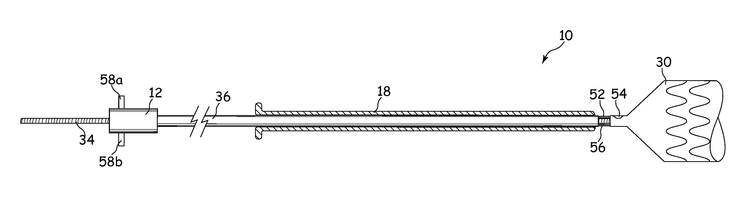
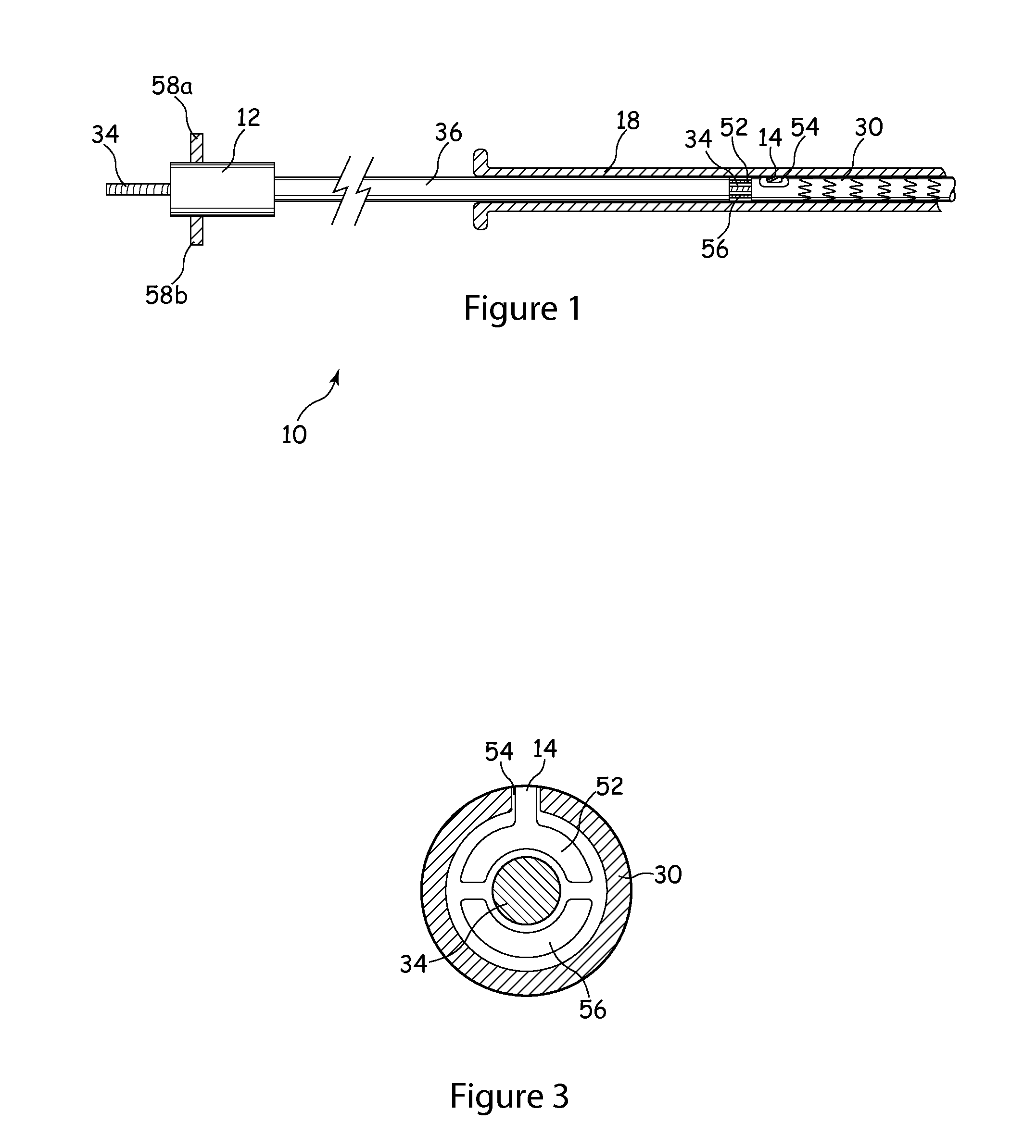
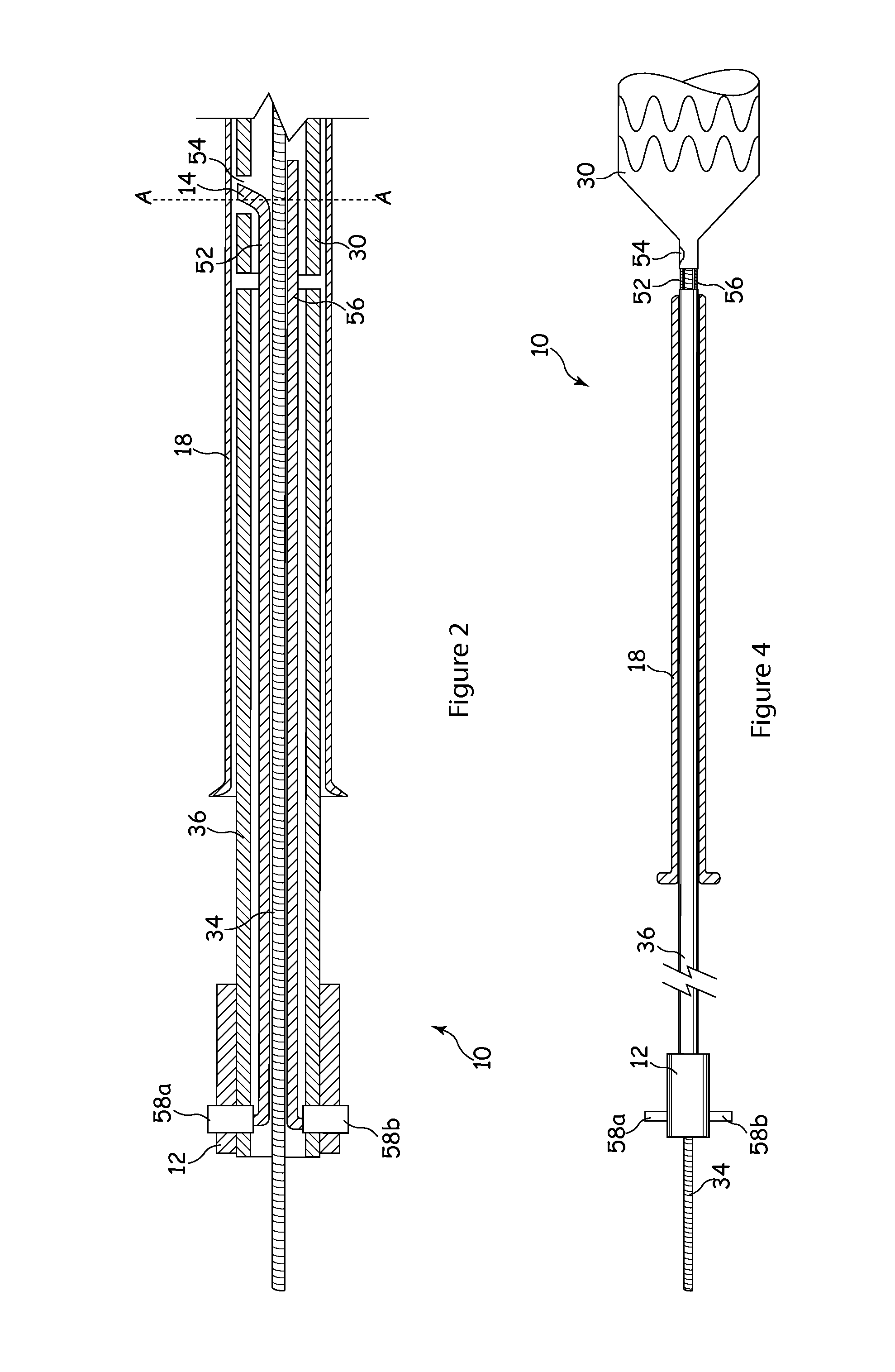
[0029]It is to be understood that the Figures are schematic and do not show the various components to their actual scale. In many instances, the Figures show scaled up components to assist in the understanding of the features disclosed therein.

[0030]In this description, when referring to a deployment assembly, the term distal is used to refer to an end of a component which in use is furthest from the surgeon during the medical procedure, including within a patient. The term proximal is used to refer to an end of a component closest to the surgeon and in practice in or adjacent an external manipulation part of the deployment or treatment apparatus.

[0031]On the other hand, when referring to an implant such as a frame or an occlusion device, the term proximal refers to a location that in use is closest to the patient's heart, in the case of a vascular implant, and the term distal refers to a location furthest from the patient's heart.

[0032]The delivery assembly 10 shown in FIG. 1 inclu...


PUM


Abstract

A delivery assembly (10) for an implant (30) includes a release mechanism comprising a locking element (52) and a blocking member (56). The locking element (52) includes a latching pin (14) that engages with an eyelet (54) in the implant (30) to attach the implant (30) to a distal end of an inner catheter (36) of the deployment of the delivery assembly (10). The blocking member (56) prevents premature disengagement of the latching pin (14) from the implant (30). Withdrawal of the blocking member (56) allows disengagement of the latching pin (14) once the implant (30) has been correctly positioned within a patient's vasculature. The locking pin (52) and the blocking member (56) extend along the lumen of the inner catheter (36) from a handle (12) at the proximal end thereof, and are arranged such that a guide wire (34) is also able to extend through the lumen of the inner catheter (36). The locking pin (52) and the blocking member (56) preferably have a crescent-shaped transverse cross section. The release mechanism allows an implant (30) to be retrieved either during deployment of the implant (30) to allow the surgeon to correct any mislocation of the implant (30), or in order to remove a previously deployed temporary implant (30) from a patient.

Description

TECHNICAL FIELD[0001]The present invention relates to a release mechanism for releasing an implant from a deployment device, for example for releasing a frame or a frame with a graft. In particular the release mechanism can be used in conjunction with over-the-wire delivery of an implant. The present invention relates also to a deployment device including the release mechanism, and to an implant that may be delivered by the deployment device.BACKGROUND ART[0002]Delivery devices employing catheters have been used for medical procedures, including procedures for establishing, re-establishing or maintaining passages, cavities or lumens in vessels, organs or ducts in human and veterinary patients, occlusion of such vessels, delivering medical treatments, and other interventions. For these procedures, it is known to deliver an implant by means of a catheter, often intraluminally.[0003]Use of a guide wire over which an implant deployment device is passed in order to deliver an implant to ...

Claims


Application Information

Patent Timeline
Patent Type & Authority Applications(United States)
IPC IPC(8): A61M39/00
CPCA61F2002/9534A61F2/95
Inventor CHRISTIANSEN, FRANK K.
Owner COOK MEDICAL TECH LLC
Why Eureka
Try Eureka