System and method for controlling a turbine blade

a technology of turbine blades and control systems, applied in the direction of machines/engines, process and machine control, instruments, etc., can solve the problems of mechanical commutation dc motor solutions, safety hazards to life and property, and catastrophic failure of machines

Active Publication Date: 2011-02-24
WINDURANCE
View PDF8 Cites 15 Cited by
  • Summary
  • Abstract
  • Description
  • Claims
  • Application Information

AI Technical Summary

Benefits of technology

[0031]These and other objects and advantages of the present invention will be readily appreciable from the following description of preferred embodiments of the invention and from the accompanying drawings and claims.

Problems solved by technology

Otherwise the turbine cannot be stopped and such loss of control can lead to catastrophic failure of the machine, and potentially pose a safety hazard to life and property.
There are at least two limitations of the mechanically commutated DC motor solution.
With DC motors the inertia tends to be high in relation to the torque and hence the system acceleration is limited substantially by the motor inertia itself.
This acceleration limit sets the overall dynamic response for the pitch actuator.
Increasing demands on pitch actuator dynamic response tends to work against long service life for the motor brushes and commutator.
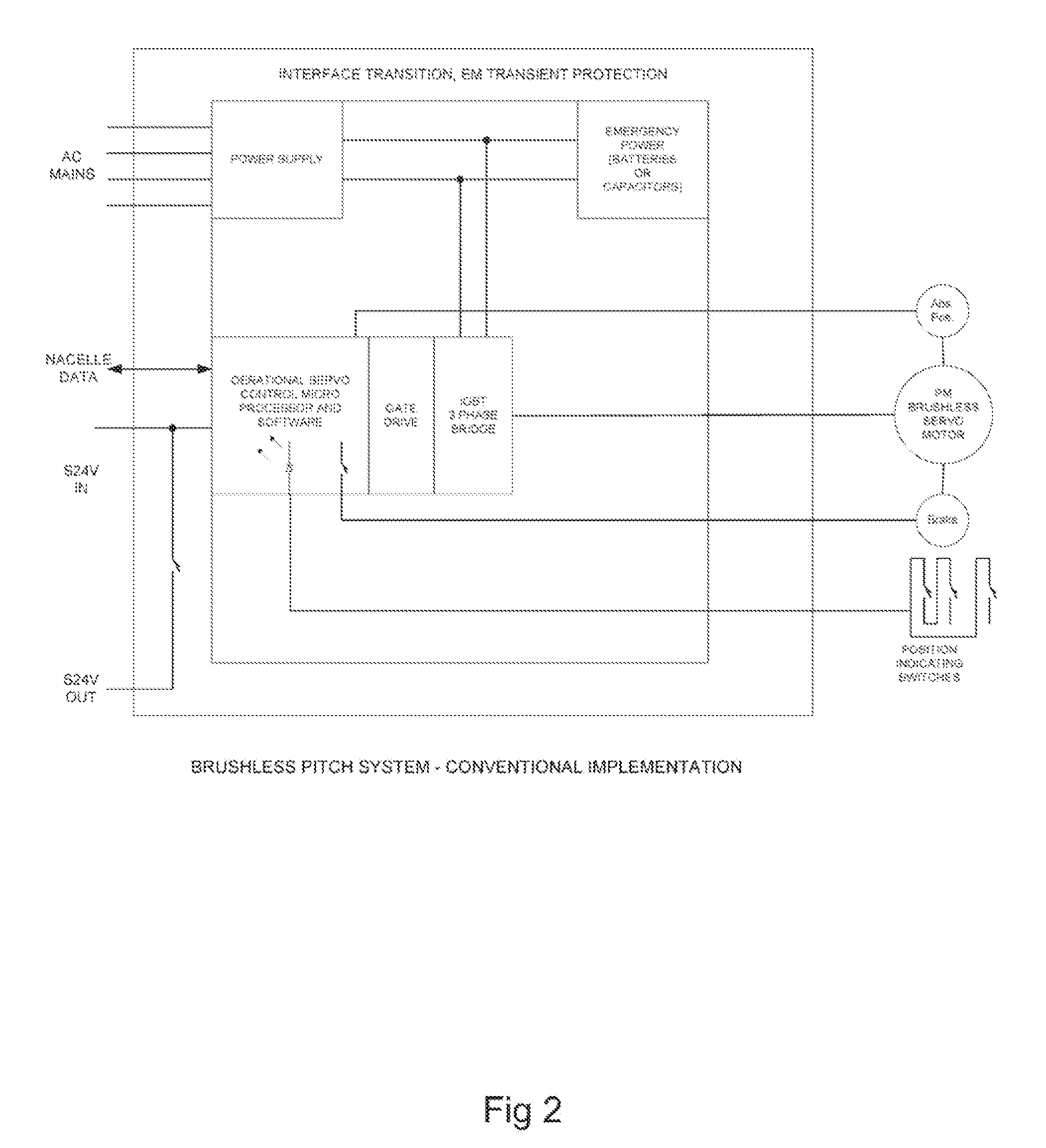
The main drawback for a typical AC motor actuator system for pitch control is its substantial weaknesses from a safety system standpoint.
1. Exceedingly high parts count for the hardware resulting in inherently lower reliability for the individual blade safety system;
2. Undesirably high level of complexity of the safety circuits leading to loss of reliability;
3. Common mode failure potential for all blades in the microprocessor functionality, application software implementation, and third party editor and compiler software tools.
4. The safety system on each blade relies on the same numerous and delicate parts and semiconductors used in the electronics for normal control, inviting common mode failure from AC mains generator disturbances, grid supply transients, or from lightning strikes. A systemic common mode failure caused by external electrical transients can result in a safety system failure on more than one blade.
5. Nearly any single point failure results in a failure of the safety system on at least one blade. While safety failure of one blade does not result in a catastrophic failure, such failure results in extraordinary impulse and fatigue conditions. These condition may offset the benefits of higher load mitigation capability, since the load case for the preceding condition must be accounted for at potentially higher frequency over the turbine design life than with the DC pitch system.

Method used


Image

  • System and method for controlling a turbine blade
  • System and method for controlling a turbine blade
  • System and method for controlling a turbine blade

Examples


Embodiment Construction

[0044]At the outset, it should be appreciated that like drawing numbers on different drawing views identify identical, or functionally similar, structural elements of the invention. While the present invention is described with respect to what is presently considered to be the preferred aspects, it is to be understood that the invention as claimed is not limited to the disclosed aspects.

[0045]Furthermore, it is understood that this invention is not limited to the particular methodology, materials and modifications described and as such may, of course, vary. It is also understood that the terminology used herein is for the purpose of describing particular aspects only, and is not intended to limit the scope of the present invention, which is limited only by the appended claims.

[0046]Unless defined otherwise, all technical and scientific terms used herein have the same meaning as commonly understood to one of ordinary skill in the art to which this invention belongs. Although any meth...


PUM


Abstract

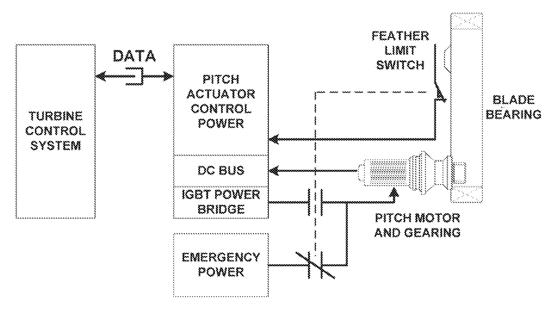
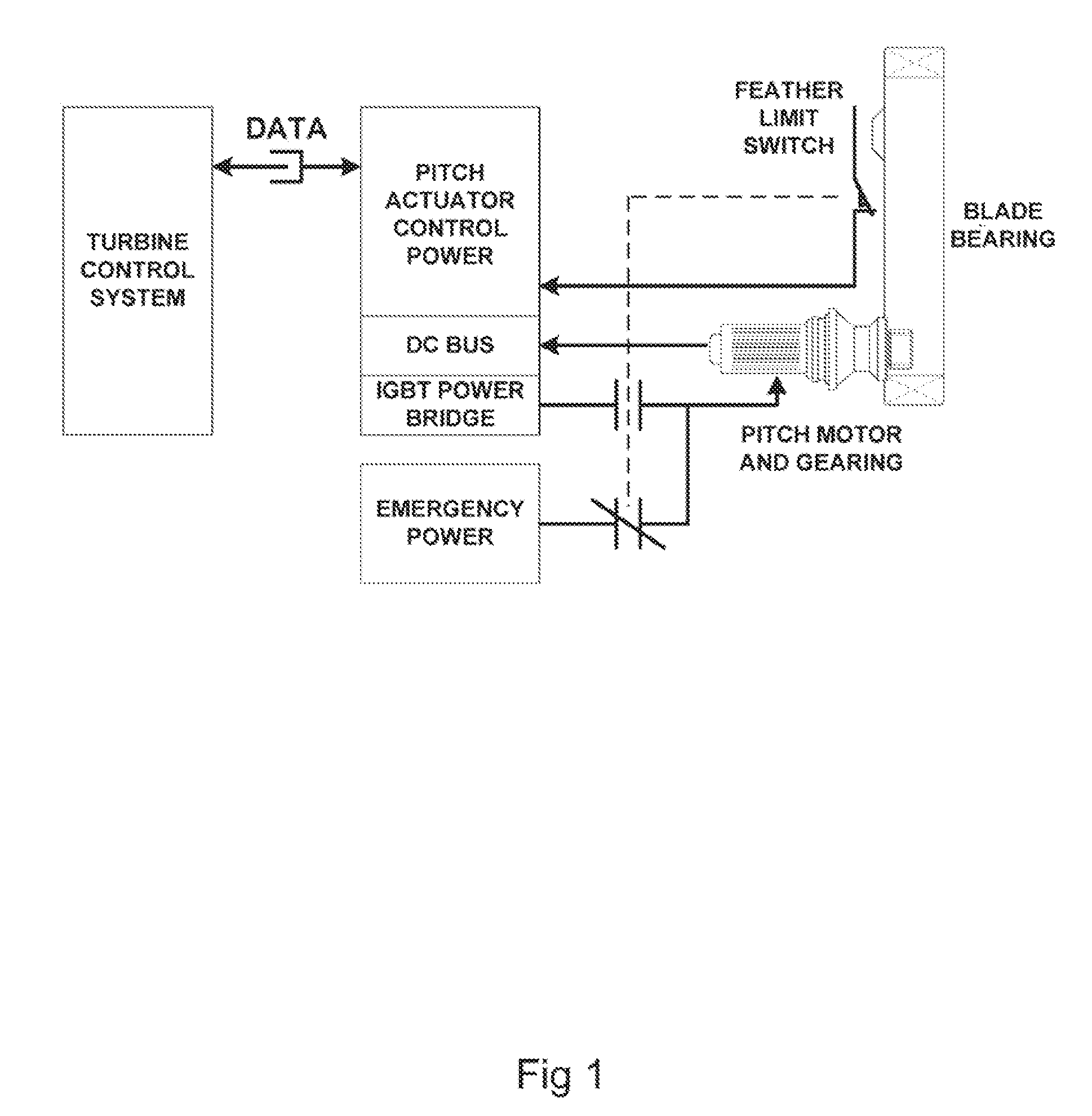
A control system for a turbine blade, including: an operational control element for generating and outputting an operational control signal, the operational control signal for non-emergency operation of a motor for controlling pitch of the turbine blade; an emergency control element, separate from and different from the operational control element, for generating and outputting an emergency control signal for emergency operation of the motor; and, an output stage element for receiving the operational and emergency control signals and for selecting one of the operational or emergency control signals, and with a means for receiving power for operation of the motor and with a means for providing the received power to the motor according to the selected operational or emergency control signal.

Description

CROSS-REFERENCE TO RELATED APPLICATIONS[0001]This application claims the benefit of International Application No. PCT / US2008 / 012366, filed Oct. 31, 2008 which claims the benefit under 35 U.S.C. §119(e) of U.S. Provisional Application No. 61 / 001,443 filed on Nov. 1, 2007 which applications are incorporated herein by reference.FIELD OF THE INVENTION[0002]The present invention relates to wind or water turbines having one or more blades and, in particular, to electrical actuation of the pitch angle of the blades. More specifically, the present invention relates to emergency control of the pitch angle for the blades.BACKGROUND OF THE INVENTION[0003]Dynamic control of blade pitch angle is used on turbines as part of an overall control system to regulate rotor speed and torque. Techniques are also employed to adjust blades to mitigate a variety of impulse and fatigue loads in response to the time varying flow velocity conditions in the field of the swept rotor area. Changes in fluid densit...

Claims


Application Information

Patent Timeline
Patent Type & Authority Applications(United States)
IPC IPC(8): G06F1/26
CPCF03D7/0224F03D7/0264Y02E10/723F05B2210/16F05B2270/107F03D7/042Y02E10/72F05B2270/328
Inventor JONES, STEPHEN P.CLELAND, ALAN DUANEROWAN, PAUL JOHN
Owner WINDURANCE
Why Eureka
Try Eureka