Wire saw device

a wire saw and wire saw technology, applied in the field of wire saw devices, can solve the problems of significant influence of nanotopography on increase in weight components on the surface of wafers, and deterioration of the quality of obtained wafers, so as to achieve the effect of simple device structure, reliable prevention of slurry splashing, and effective suppression of nanotopography and warp increas

Active Publication Date: 2011-03-03
SUMCO CORP
View PDF5 Cites 20 Cited by
  • Summary
  • Abstract
  • Description
  • Claims
  • Application Information

AI Technical Summary

Benefits of technology

[0028]According to the present invention, it is possible to provide a wire saw capable of reliably preventing slurry from splashing onto the top surface of a work and effectively suppressing increase in nanotopography and Warp, by designing the s

Problems solved by technology

However, there is a problem in such a wire saw device as described above, in that slurry supplied to the wires changes the temperature of the ingot when the ingot is cut by the wires, whereby waviness components on a wafer surface increases and the quality of the obtained wafers deteriorates.
Among these examples, increase in nanotopography significantly affects the quality of wafers.
Among these components, the component generated in the cut-starting or the cut-finishing portion of a wafer is likely to be judged as defective in the numerical judgment of nanotopography.
In particular, nanotopography in the cut-finishing portion is generally larger than nanotopography in the cut-starting portion and thus likely to exhibit the worst numerical value of nanotopography in a wafer surface and be regarded as defective in the numerical judgment.
However, the wire saw device described in JP 2008-302618 needs two nozzles and the temperatures of slurries released from these nozzles have to be controlled, respectively, whereby the device structure is complicated and the device itself is quite expensive.
Yet further, since the slurry splashed on the top surface of an ingot is supplied again to the ingot, slurry supply becomes too much, making it difficult to appropriately control the temperature of the ingot and thus increasing nanotopography and Warp, which results in deterioration of wafer quality.
However, the wire saw device disclosed in JP 2007-273711 has a problem in that the catching member thereof cannot sufficiently catch slurry released from the nozzle and a portion of the slurry splashes on the top surface of the work, whereby nanotopography and Warp inc

Method used


Image

  • Wire saw device
  • Wire saw device
  • Wire saw device

Examples


examples

[0045]Next, a wafer obtained by cutting an ingot by using a wire saw device of the present invention and a wafer obtained by cutting an ingot by using a conventional wire saw device lacking a slurry blocking plate are evaluated regarding nanotopography and Warp thereof, respectively.

[0046](Production Condition)

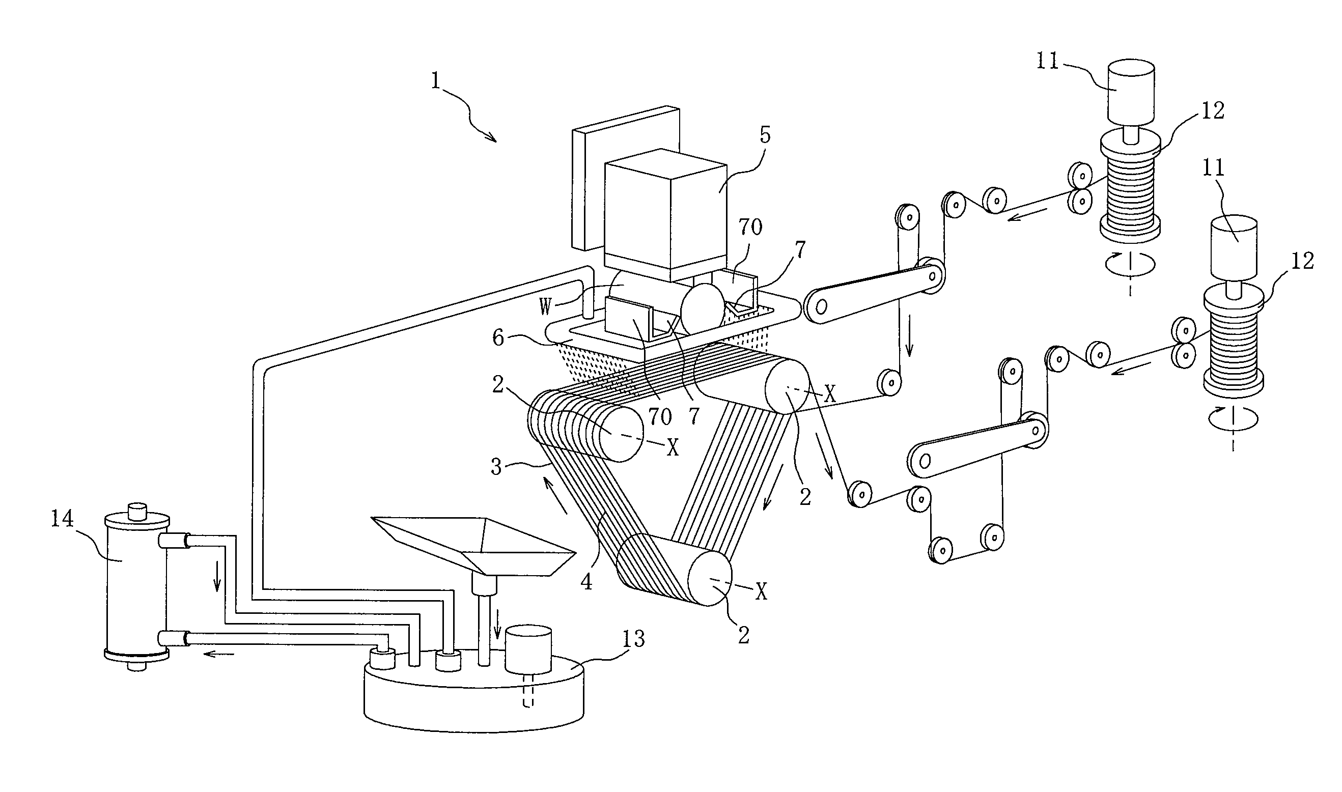
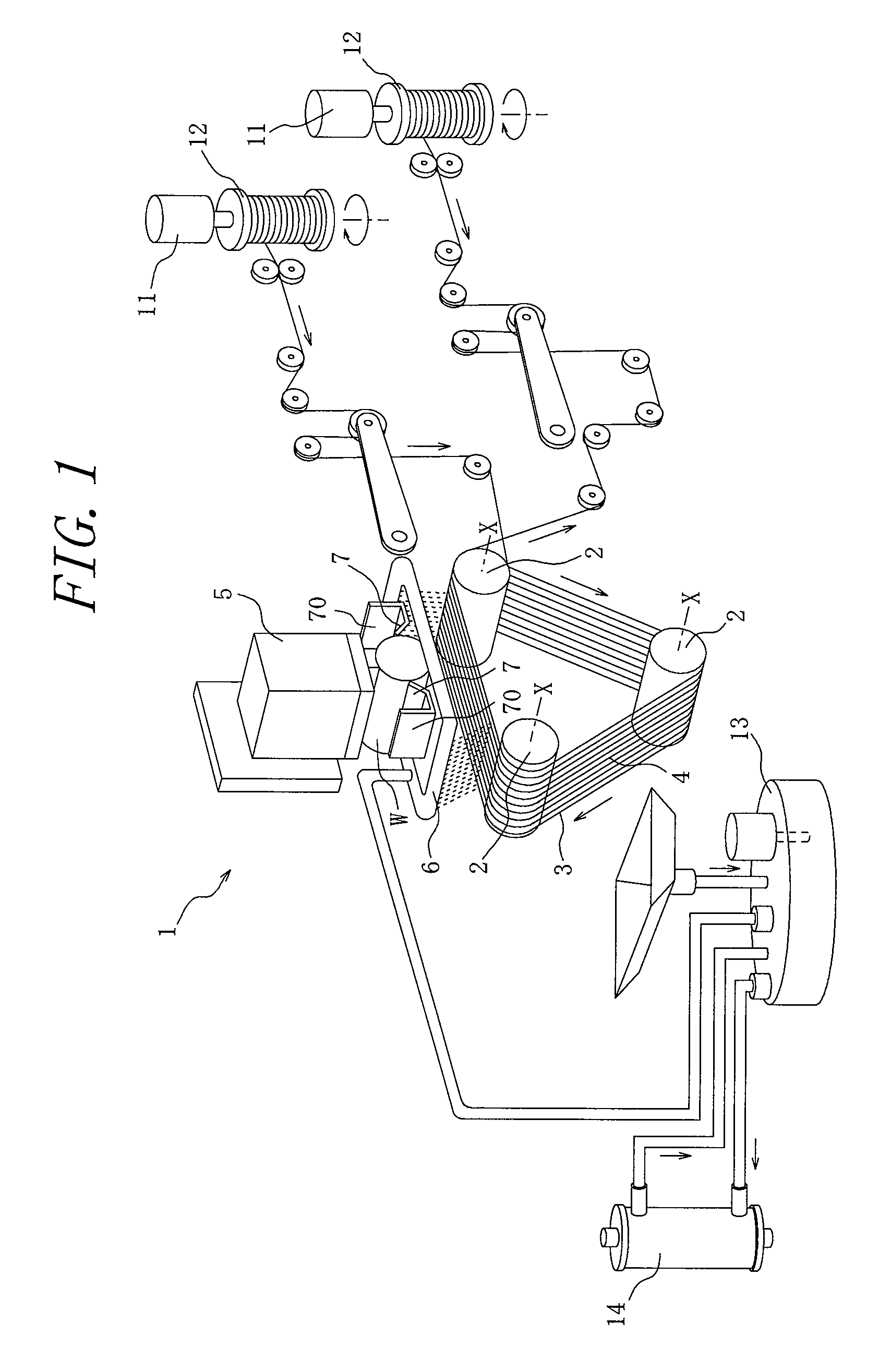
[0047]Cutting of an ingot is carried out by using a wire saw device of the present invention as shown in FIG. 1 and a conventional wire saw device lacking a slurry blocking plate, respectively, under the cutting conditions shown in Table 1 below. The ingot for use in the cutting operation is a silicon ingot having diameter of 300 mm, and wafers each having thickness of approximately 0.7 to 1.0 mm are cut out therefrom.

[0048]FIG. 4 is a view showing change in temperature of an ingot measured by a radiation thermometer when the ingot is cut by using a wire saw device of the present invention and change in temperature of an ingot measured by a radiation thermometer when the ingot...


PUM

PropertyMeasurementUnit
Temperatureaaaaaaaaaa
Massaaaaaaaaaa
Mass flow rateaaaaaaaaaa

Abstract

An object of the present invention is to provide at a relatively cheap price a wire saw device capable of effectively preventing slurry from splashing onto the top surface of a work and effectively suppressing increase in nanotopography and Warp. The wire saw device 1 of the present invention has: a group of multiple wires 4 formed by suspending a wire 3 over a set of rollers 2, 2, 2 separate from each other so as to be aligned in a cutting side thereof in parallel to one another in the roller shaft direction X and capable of running in a direction orthogonal to the roller shaft direction; a work holding portion 5 for holding a work W and moving the work W in a direction of pushing the work W with respect to the group of multiple wires 4; and a nozzle 6 for supplying slurry to the group of multiple wires 4 from at least a position on the upperstream side in the running direction of the multiple wires 4, with respect to a path along which the work W is pushed into the wire 3. Further, the wire saw device 1 is provided with a slurry blocking plate 7, extending in the direction along which the multiple wires 4 are aligned in parallel to one another, and pivotably fixed at a base point located at least on the side at which the nozzle 6 is provided and above the multiple wires 4, such that the slurry blocking plate 7 falls, around the base point, on the work W in the direction of pushing the work W with respect to the multiple wires 4.

Description

BACKGROUND OF THE INVENTION[0001]1. Field of the Invention[0002]The present invention relates to a wire saw device for cutting out a number of wafers from a silicon ingot, an ingot of a compound semiconductor material, or the like, and particularly to a wire saw device having a structure which allows wafer cut out from an ingot to maintain high quality.[0003]2. Description of the Related Art[0004]A wafer for use in a semiconductor substrate is produced by slicing a material such as a silicon ingot or an ingot of a compound semiconductor material. As a result of recent increase in size of such an ingot, the conventional cutting process of an ingot by an inner-diameter blade slicer has been increasingly replaced with a method of producing a large number of wafers by simultaneous slicing process using a wire saw device. A piece of a material, including such an ingot as described above, which is subjected to a cutting process by a wire saw, is generally referred to a “work”.[0005]A wire...

Claims


Application Information

Patent Timeline
IPC IPC(8): B28D5/04B28D7/00
CPCB28D5/007B28D7/00B28D5/045Y02P70/10
Inventor FUKUDA, MASAKIFUTAMURA, HIROYASUSHINDOU, RYOUJI
Owner SUMCO CORP
Why Eureka
Try Eureka