Solar cell and solar cell module

Inactive Publication Date: 2011-03-03
SANYO ELECTRIC CO LTD
View PDF1 Cites 51 Cited by
  • Summary
  • Abstract
  • Description
  • Claims
  • Application Information

AI Technical Summary

Benefits of technology

[0045]According to the second aspect, the yi

Problems solved by technology

This may increase the occurrence of cracks in the so

Method used


Image

  • Solar cell and solar cell module
  • Solar cell and solar cell module
  • Solar cell and solar cell module

Examples


Example

First Embodiment

[0064]A solar cell module of a first embodiment of the invention will be described with reference to FIGS. 1 to 5.

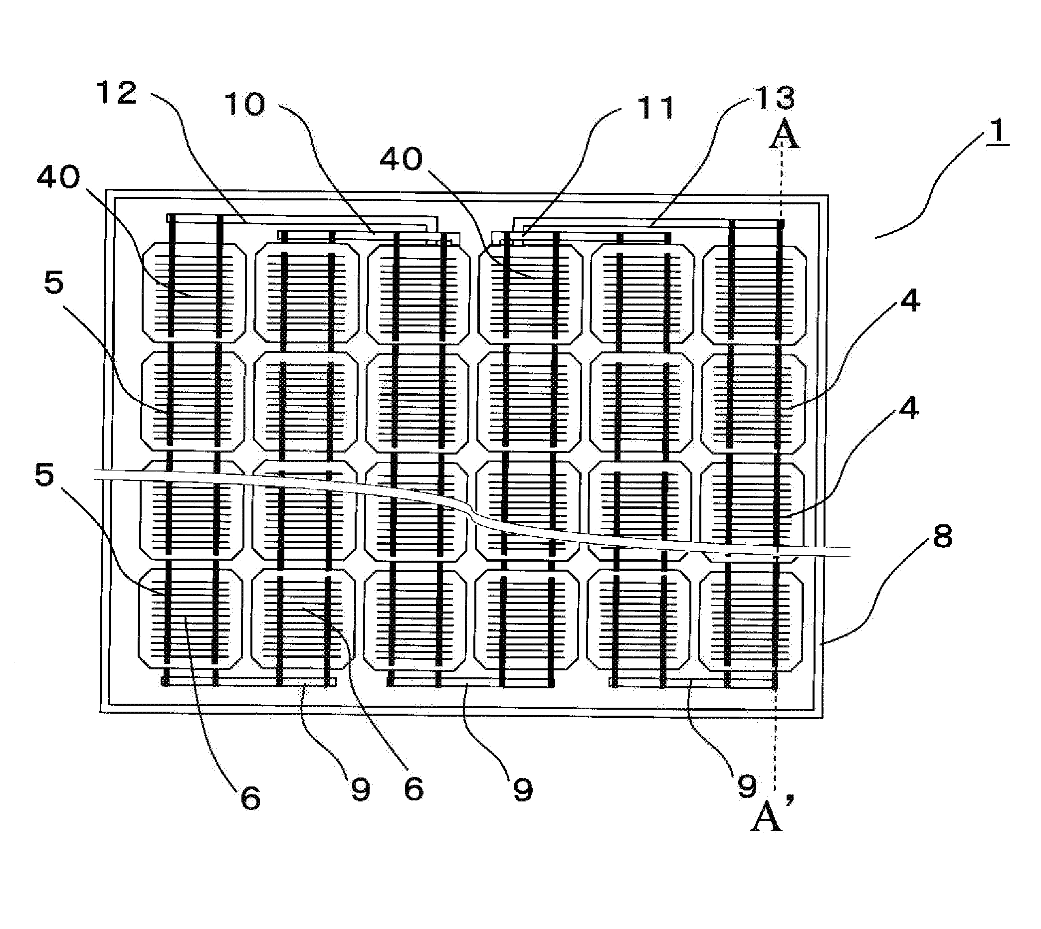
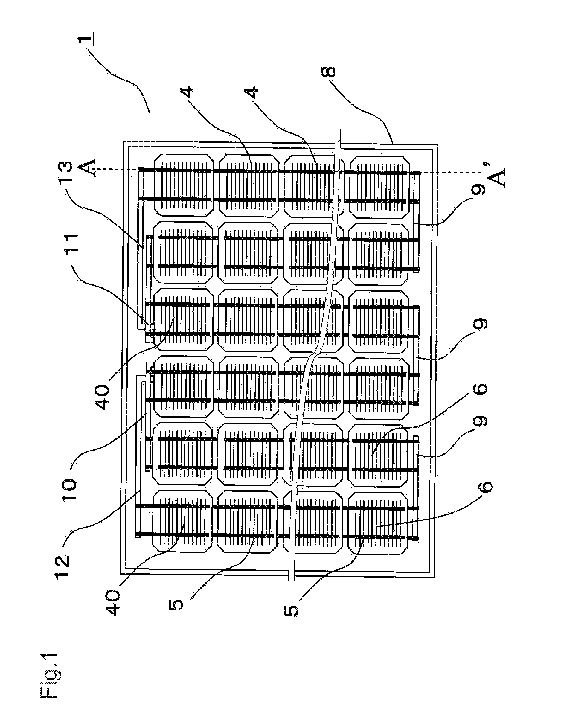
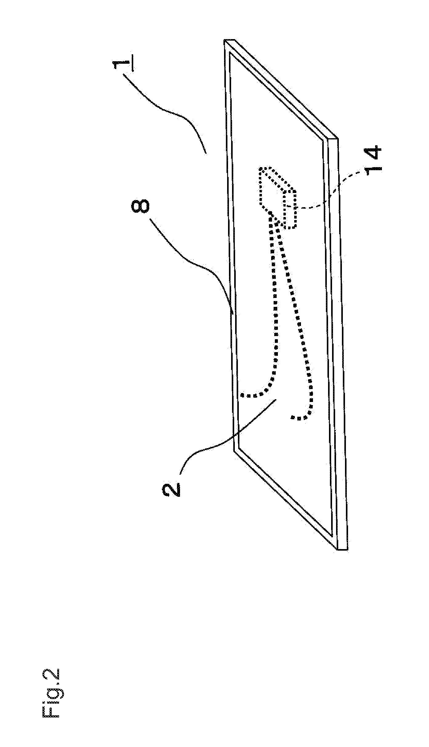
[0065]FIG. 1 is a top view of the solar cell module of the first embodiment of the invention. FIG. 2 is a perspective view of the solar cell module of the first embodiment. FIG. 3 is a sectional view of a part of the solar cell module along line A-A′ in FIG. 1. FIG. 4A is a top view of a solar cell in the solar cell module of the first embodiment, FIG. 4B is a bottom view of the solar cell, and FIG. 4C is a sectional view of the solar cell along line B-B′ in FIGS. 4A and 4B. FIG. 5 is a sectional view of a part of the solar cell module of the first embodiment, for explaining the connection between the solar cell and conductive connection members.

[0066]In FIGS. 1 to 5, reference number 1 designates a solar cell module. Solar cell module 1 includes a rectangular plate-like structure and frame body 8 made of metal such as aluminum and configured to support t...

Example

Second Embodiment

[0097]A solar cell module of the second embodiment of the invention will be described with reference to FIGS. 6A, 6B, 6C and 7. FIG. 6A is a top view of a solar cell in the solar cell module, FIG. 6B is a bottom view of the solar cell, and FIG. 6C is a sectional view of a part of the solar cell with connection members connected thereto taken along line C-C′ in FIGS. 6A and 6B. FIG. 7 is a sectional view of a part of the solar cell module. Note that differences from the first embodiment are mainly described in the second embodiment.

[0098]The second embodiment is different from the first embodiment in that bus bar electrodes of rear surface electrode 19 are shorter than those of the first embodiment in the longitudinal direction and are formed in the vicinity of the edge of the rear surface of solar cell 4. The other configurations are the same as those of the first embodiment and are designated in FIGS. 6A to 7 by the same reference numerals as those of the first emb...

Example

Third Embodiment

[0102]A solar cell module of the third embodiment of the invention will be described with reference to FIGS. 8A, 8B, 8C, and 9. FIG. 8A is a top view of a solar cell of the solar cell module, FIG. 8B is a bottom view of the solar cell, and FIG. 8C is a sectional view of a part of the solar cell along line D-D′ in FIGS. 8A and 8B. FIG. 9 is a sectional view of a part of the solar cell module of the third embodiment, for explaining the connection between the solar cell and conductive connection members. Note that differences from the first embodiment are mainly described in the third embodiment.

[0103]The third embodiment is different from the first embodiment in that front surface electrode 17 has no bus bar electrode (that is, the front surface electrode 17 has no bus bar structure). The other configurations in the third embodiment are the same as those of the first embodiment and are designated in FIGS. 8A to 9 by the same reference numerals.

[0104]With reference to F...


PUM

PropertyMeasurementUnit
Temperatureaaaaaaaaaa
Electrical conductoraaaaaaaaaa
Areaaaaaaaaaaa

Abstract

A solar cell includes: an photoelectric conversion body including a first main surface and a second main surface opposed to the first main surface; a first electrode provided on the first main surface; a second electrode provided on the second main surface; a first conductive connection member connected with the first electrode for connecting the solar cell and another solar cell, wherein the first conductive connection member includes a conductive soft layer at an area facing the first electrode, and the first electrode includes a conductive soft layer at an area facing the first conductive connection member; and a first resin adhesive bonding the first conductive connection member to the first electrode in such a manner that the conductive soft layer of the first electrode and the conductive soft layer of the first conductive connection member abut on each other.

Description

CROSS REFERENCE TO RELATED APPLICATIONS[0001]This application of the invention titled “Solar Cell and Solar Cell Module” is based upon and claims the benefit of priority under 35 USC 119 from prior Japanese Patent Application No. 2009-200687, filed on Aug. 31, 2009; the entire contents of which are incorporated herein by reference.BACKGROUND OF THE INVENTION[0002]1. Field of the Invention[0003]The invention relates to a solar cell and a solar cell module.[0004]2. Description of Related Art[0005]A solar cell system having solar cells is expected to be a new energy conversion system that converts light from the sun into electricity. In recent years, active use of solar cell systems has been increasing as a general household power supply and a large-scale power generation plant.[0006]Currently, under the situation described above, research and development for cost reduction of solar cell systems are actively in progress in order to further spread their use.[0007]FIG. 14A is a perspecti...

Claims


Application Information

Patent Timeline
IPC IPC(8): H01L31/042H01L31/04H01L31/18
CPCH01L31/0504Y10T156/10Y02E10/50
Inventor NISHIWAKI, TAKESHI
Owner SANYO ELECTRIC CO LTD
Why Eureka
Try Eureka