
Blind device using solar cells

a solar cell and blinding technology, applied in the direction of curtain suspension devices, pv power plants, door/window protective devices, etc., can solve the problems of insufficient practical use, portion shaded from light cannot generate electricity, and the voltage obtained from a unit solar cell is about 1 v or less, so as to achieve the effect of minimizing power loss

Inactive Publication Date: 2011-03-03
ELECTRONICS & TELECOMM RES INST
View PDF10 Cites 41 Cited by
  • Summary
  • Abstract
  • Description
  • Claims
  • Application Information

AI Technical Summary

Benefits of technology

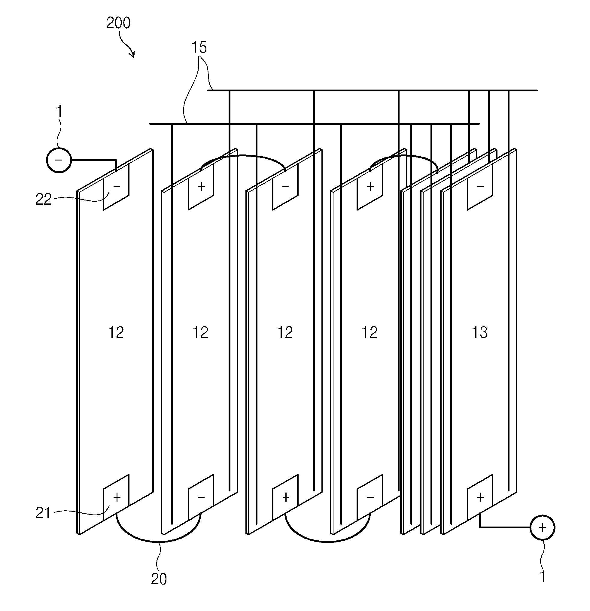
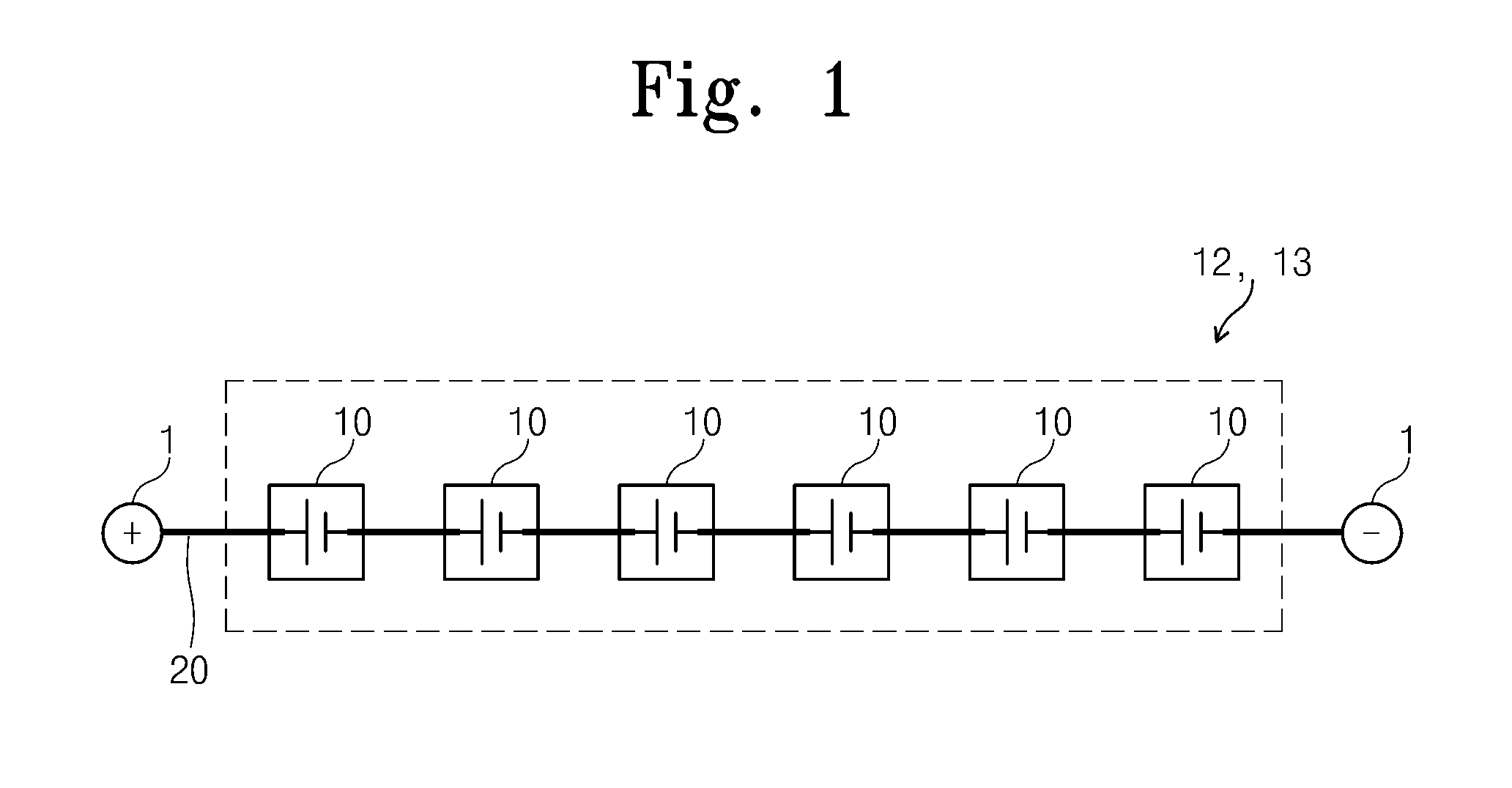
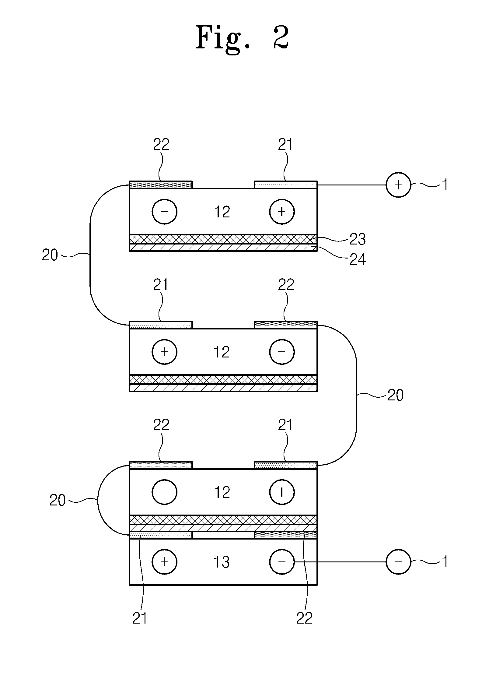
The present invention is about a blind device that uses solar cells to generate power. The invention includes multiple solar cell panels and electric wires that connect them in series. Each solar cell panel has two electrodes on its surface, and a bypass device that short-circuits the electrodes when no light is incident on the panel. The technical effect of this invention is to minimize power loss and maximize the amount of sunlight that can be captured and converted into electricity.

Problems solved by technology

The amount of voltage obtained from a unit solar cell is about 1 V or less, which is insufficient for any practical use.
However, when a portion of solar cells is collapsed or overlapped because of an insufficient space or the adjustment of light intensity, the portion shaded from light cannot generate electricity.
When solar cells are connected to each other in series, a non-generating solar cell functioning as a resistor degrades the generating efficiency of a whole system, and heat generated from the non-generating solar cell may reduce the service life of the system and damage the system.
Typically, a unit solar cell has an electromotive force ranging from about 0.5 V to about 1 V, which is similar to a voltage drop value of a diode, so that it is inefficient to dispose a bypass diode on each cell.
In this case, voltage drop, which inevitably occurs in a diode, causes power loss through a bypass.
When a bypass diode is attached to two or more slat type panels, some of the panels cause power loss and are heated according to overlapping state of the panels.

Method used


Image

  • Blind device using solar cells
  • Blind device using solar cells
  • Blind device using solar cells

Examples


Embodiment Construction

[0017]Preferred embodiments of the present invention will be described below in more detail with reference to the accompanying drawings. The present invention may, however, be embodied in different forms and should not be constructed as limited to the embodiments set forth herein. Rather, these embodiments are provided so that this disclosure will be thorough and complete, and will fully convey the scope of the present invention to those skilled in the art. Like reference numerals refer to like elements throughout.

[0018]In the following description, the technical terms are used only for explain a specific exemplary embodiment while not limiting the present invention. The terms of a singular form may include plural forms unless referred to the contrary. The meaning of “include,”“comprise,”“including,” or “comprising,” specifies a property, a region, a fixed number, a step, a process, an element and / or a component but does not exclude other properties, regions, fixed numbers, steps, p...


PUM


Abstract

Provided is a blind device using solar cells. The blind device includes a plurality of solar cell panels, and a plurality of electric wires connecting the solar cell panels to each other in series. Each of the solar cell panels includes a first electrode and a second electrode on a surface, and a bypass device short-circuiting the first and second electrodes when light is not incident to the solar cell panel.

Description

CROSS-REFERENCE TO RELATED APPLICATIONS[0001]This U.S. non-provisional patent application claims priority under 35 U.S.C. §119 of Korean Patent Application No. 10-2009-0080496, filed on Aug. 28, 2009, the entire contents of which are hereby incorporated by reference.BACKGROUND OF THE INVENTION[0002]The present invention disclosed herein relates to a blind device using solar cells, and more particularly, to a blind device using solar cells, which improves the generating efficiency of the solar cells.[0003]Recently, the importance of development of next generation clean energy resources is being emphasized because of issues such as the global warming due to carbon dioxide emission form fossil fuels, accidents of nuclear power plants, and radioactive contamination due to radioactive waste. Specifically, photovoltaic power generating systems (solar cells) using unlimited and semi-permanent sunlight are being regarded with much interest as next generation energy generating systems.[0004]...

Claims


Application Information

Patent Timeline
Patent Type & Authority Applications(United States)
IPC IPC(8): E06B9/68H01L31/042
CPCE06B9/28E06B9/36E06B9/386E06B9/42H02S30/20H01L31/02021H01L31/042Y02E10/50E06B2009/2476H02S40/36E06B2009/6827E06B2009/285
Inventor CHU, MOO JUNGOH, SOO YOUNG
Owner ELECTRONICS & TELECOMM RES INST
Learn More