Electricity Generating Assembly

Inactive Publication Date: 2011-03-03
GREEN WILLIAM M
View PDF99 Cites 14 Cited by
  • Summary
  • Abstract
  • Description
  • Claims
  • Application Information

AI Technical Summary

Benefits of technology

[0007]It has now been found that by controlling movement of the shutters for an electricity generating assembly by an electronic motor, the shutters may be opened and closed under variable conditions independently of the shutter structure design.

Problems solved by technology

Additionally, a sensor may be connected to a motor to close the shutters due to high winds or other environmental conditions that could damage the fan blades.

Method used


Image

  • Electricity Generating Assembly
  • Electricity Generating Assembly
  • Electricity Generating Assembly

Examples


Embodiment Construction

[0063]The present invention is described more fully with reference to the accompanying drawings, in which exemplary embodiments of the invention are shown. The present invention may, however, be embodied in many different forms and should not be construed as being limited to the exemplary embodiments set forth herein; rather, these exemplary embodiments are provided so that this disclosure is thorough and complete, and conveys the concept of the invention to those skilled in the art.

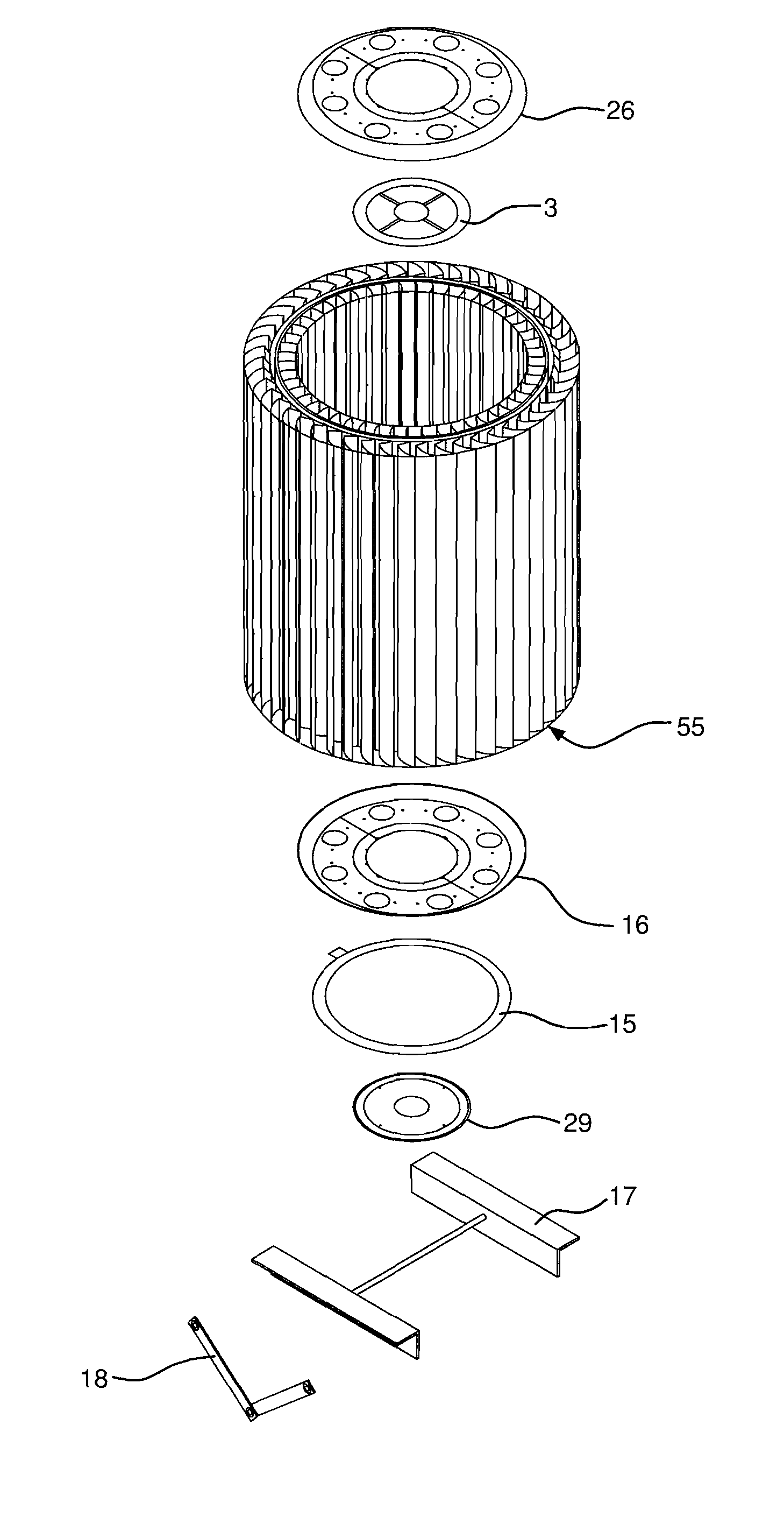
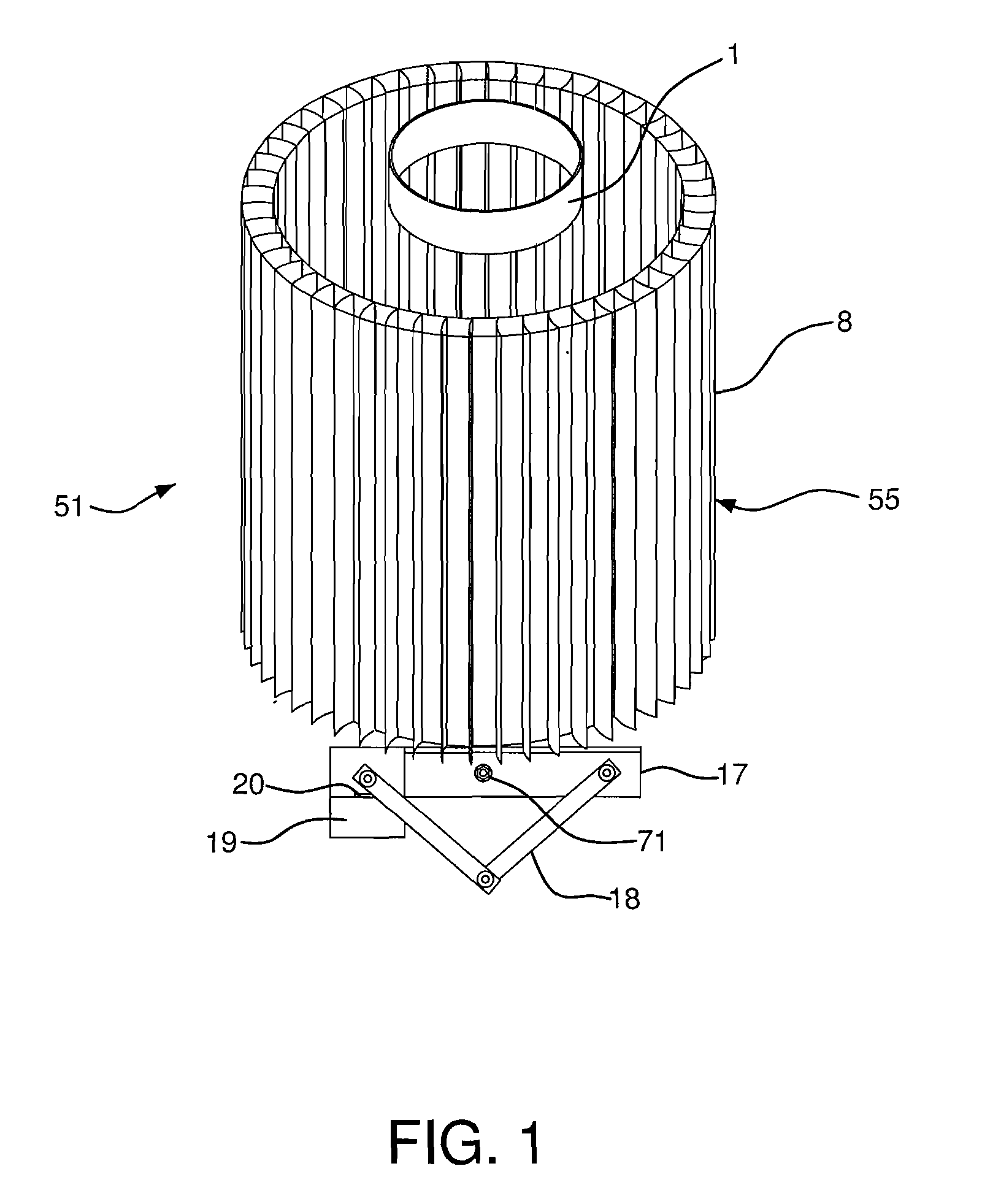
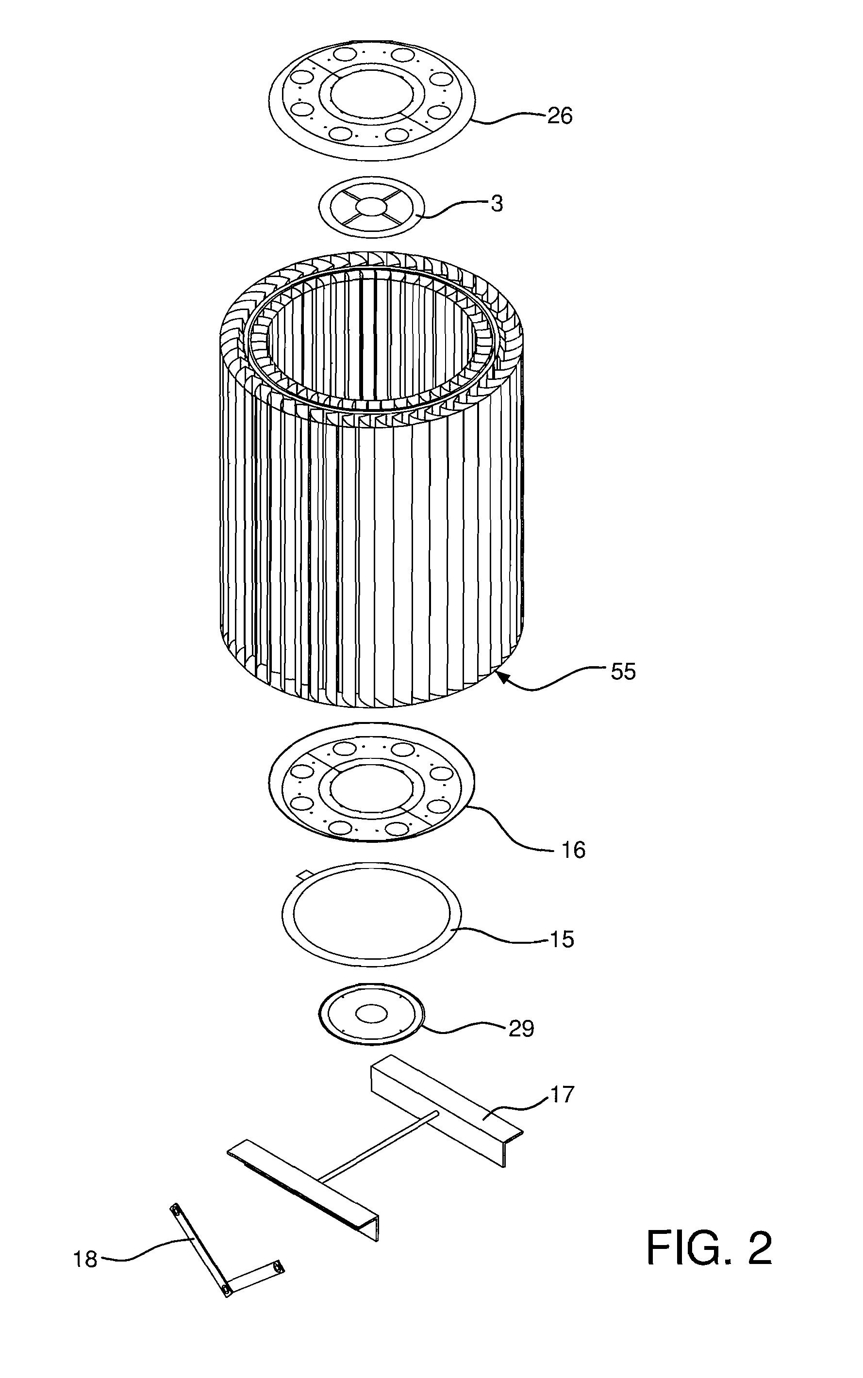
[0064]In a first exemplary embodiment of the present invention, the electricity generating assembly 55 is mounted to a pole 30 and the generator 19 is disposed externally of the plurality of fan blades 5, as shown in FIGS. 1 and 3. The generator 19 may include a gear box, transmission, and / or other suitable gear and power transmitting assemblies

[0065]As shown in FIGS. 1-4, the electricity generating assembly 55 is mounted to a support, such as a telephone pole 30. A plurality of fan blades 5 are disposed...


PUM


Abstract

An electricity generating assembly includes a first turbine having a first plurality of fan blades and a second turbine having a second plurality of fan blades. A first rotor is connected to the first turbine and rotatable with the first turbine. A second rotor is connected to the second turbine and is rotatable with the second turbine. The first and second turbines are rotatably connected to a shaft such that rotation of the first and second turbines cause rotation of the shaft, wherein the first and second turbines rotate in opposite directions.

Description

CROSS REFERENCE TO RELATED APPLICATIONS[0001]This application is a continuation-in-part of U.S. patent application Ser. No. 11 / 867,436, now U.S. Pat. No. 7,816,802, filed Oct. 4, 2007, which claims the benefit under 35 U.S.C. §119(e) of provisional application Ser. No. 60 / 849,842, filed Oct. 6, 2006 and 60 / 915,591, filed May 2, 2007, the entire disclosures of both of which are hereby incorporated by reference.FIELD OF THE INVENTION[0002]The present invention relates to an electricity generating assembly that utilizes fluid currents or flow to produce electricity. More particularly, the present invention relates to a wind generator assembly having an electrically driven shutter assembly. Furthermore, the present invention relates to a electricity generating assembly that uses water to produce electricity. Still more particularly, the present invention relates to an electricity generating assembly that is remotely operable.BACKGROUND OF THE INVENTION[0003]Wind generators have long exi...

Claims


Application Information

Patent Timeline
Patent Type & Authority Applications(United States)
IPC IPC(8): H02K7/18
CPCF03D3/005F03D3/02F03D11/04F05B2240/215Y02E10/74H02K5/00H02K7/183Y02E10/728F05B2240/911F03D13/20Y02E10/727F03D3/04F03D9/007F03D9/008F03D9/11F03D9/25F03D9/34F03D13/10F03D13/25
Inventor GREEN, WILLIAM M.
Owner GREEN WILLIAM M
Why Eureka
Try Eureka