Switching inverters and converters for power conversion

Active Publication Date: 2011-03-03
GENERAL ELECTRIC CO
View PDF6 Cites 11 Cited by
  • Summary
  • Abstract
  • Description
  • Claims
  • Application Information

AI Technical Summary

Benefits of technology

[0024]As noted, electronic devices generally require some type of power conversion in order to operate and there is always a need for greater efficiency and control of the power conversion. Furthermore, there is a continual objective of providin

Problems solved by technology

They are designed with active gain device, usually a transistor, operating in the “linear region” a condition that results in significant quiescent power dissipation.
However, such high frequency operation tends to decrease the efficiency, and there are various soft switching techniques that have been developed to reduce the losses associated with the switching.
The latter is heavily dependent on physics and material science, and furthermore appears to be subject to fundamental limitations such as breakdown voltage and permittivity for capacitors, and saturation flux density and permeability for inductors.
Up to a point, increased switching frequency yields increases power density, however as switching frequency continues to increase, issues arise which detract from these gains.
These issues include increased switching losses, proximity losses and core losses in magnetic components, and problems with parasitic reactances.
While these can be mitigated to some extent, the inefficiency issues tend to dominate the converter design, and further increases in switching frequency increase cost and losses with no attendant increase, or even a decrease, in power dens

Method used


Image

  • Switching inverters and converters for power conversion
  • Switching inverters and converters for power conversion
  • Switching inverters and converters for power conversion

Examples


Embodiment Construction

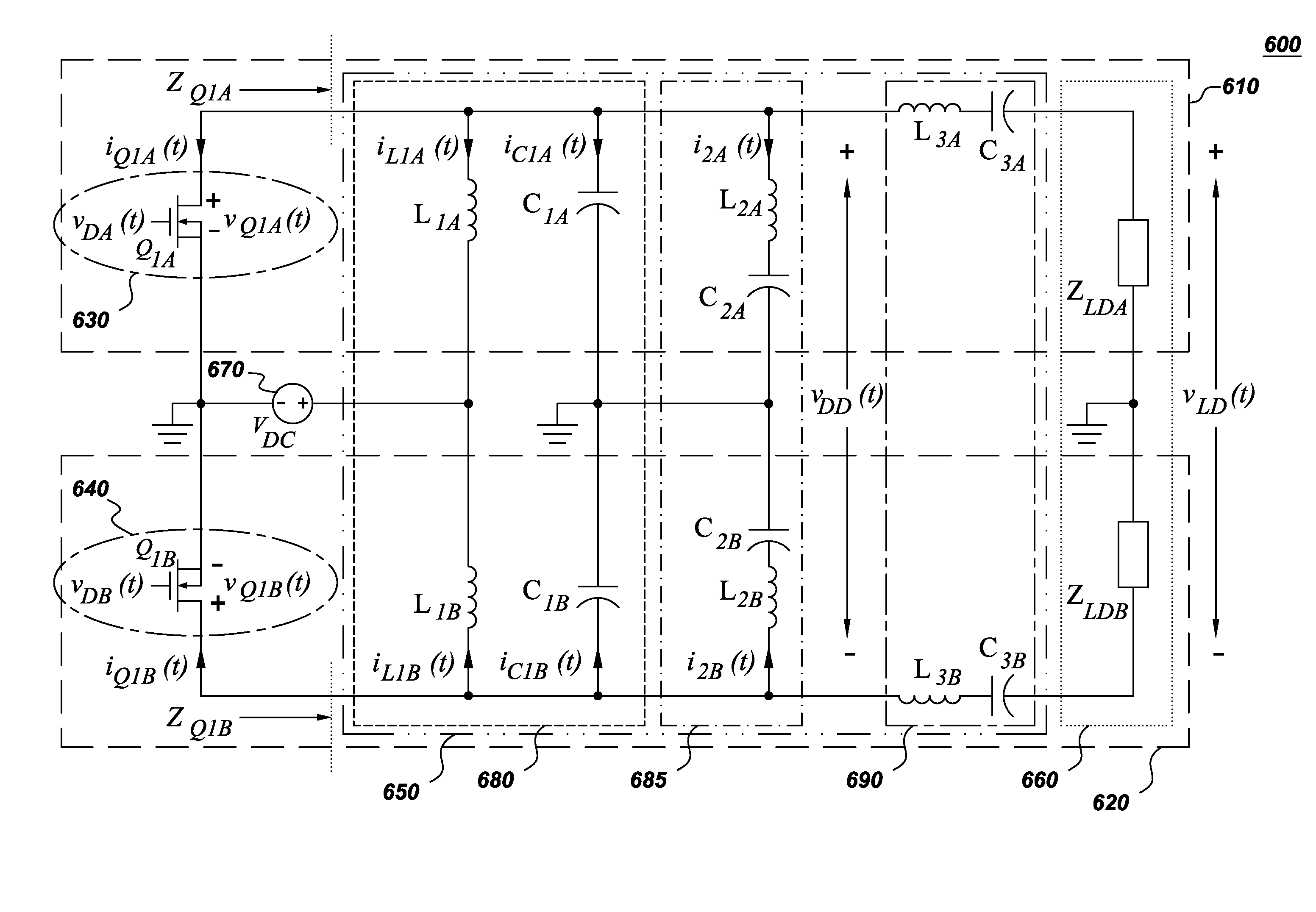
[0043]One embodiment provides circuits and techniques useful for switching inverter operation employing a tuned resonant network that operates at radio frequencies and which alleviates many of the deficiencies of the conventional designs. It is especially useful when operation at radio frequencies is desirable or necessary based on the particular application.

[0044]In one example, the circuit is developed by extending single-transistor class EF2 inverters into a push-pull circuit with a coupling that provides for independently tuning the harmonics of each section. In one aspect the circuit decouples the tuning of even and odd harmonics of the switching waveform, thus providing additional flexibility in the circuit design. Various embodiments provide for a reduction in the number and size of components, DC flux cancellation in magnetic cores, and a doubling of the ripple frequency.

[0045]A further embodiment of the present inverter is based on the class (converter that is herein classi...


PUM


Abstract

A switching inverter having two single-ended EF2 inverter sections coupled together with a shared ground and partially shared tunable resonant network that is coupled to at least one load, wherein each inverter section comprises a switching section, and wherein the shared tunable network section allows independent tuning of an impedance seen by the corresponding switching section thereby independently tuning even and odd harmonics of the switching frequency.

Description

BACKGROUND[0001]With the vast proliferation of electronic devices of increasing complexity, there is a continual effort to augment the power conversion circuitry. Two of the main types of power conversion circuitry are power amplifiers and power converters. Power amplifiers are widely used in telecommunication and industrial applications and have found use as the front-end stage in high performance dc-dc converters. Depending on their mode of operation, power amplifiers can be classified in two families, namely linear power amplifiers and switched mode amplifiers. Linear power amplifiers are commonly used because of their simplicity, linearity, and good dynamic performance. They are designed with active gain device, usually a transistor, operating in the “linear region” a condition that results in significant quiescent power dissipation. The relatively poor efficiency of linear power amplifiers makes them better suited for applications where linearity is important and the ensuing po...

Claims


Application Information

Patent Timeline
IPC IPC(8): H02M7/538H02M3/335
CPCH02M3/1588H02M7/5381Y02B70/1466Y02B70/1441Y02B70/1425Y02B70/10H02M7/53806
Inventor GLASER, JOHN STANLEYDAVILA, JUAN MANUEL RIVAS
Owner GENERAL ELECTRIC CO
Why Eureka
Try Eureka