Wood material drying plant comprising a rotary dryer

a drying plant and rotary dryer technology, applied in the direction of laundry driers, lighting and heating equipment, washing apparatus, etc., can solve the problems of high operating costs of the fabric filter of u.s. pat. no. 5,603,751 and achieve the effect of reducing operating problems and reducing energy consumption

Inactive Publication Date: 2011-03-10
ANDRITZ TECH & ASSET MANAGEMENT
View PDF12 Cites 12 Cited by
  • Summary
  • Abstract
  • Description
  • Claims
  • Application Information

AI Technical Summary

Benefits of technology

[0006]A novel wood material drying plant has been conceived which is efficient with

Problems solved by technology

The volatile organic substances may cause problems in downstream equipment which is operative for cleaning the spent drying gas leaving the rotary dryer.
The op

Method used


Image

  • Wood material drying plant comprising a rotary dryer
  • Wood material drying plant comprising a rotary dryer
  • Wood material drying plant comprising a rotary dryer

Examples


Embodiment Construction

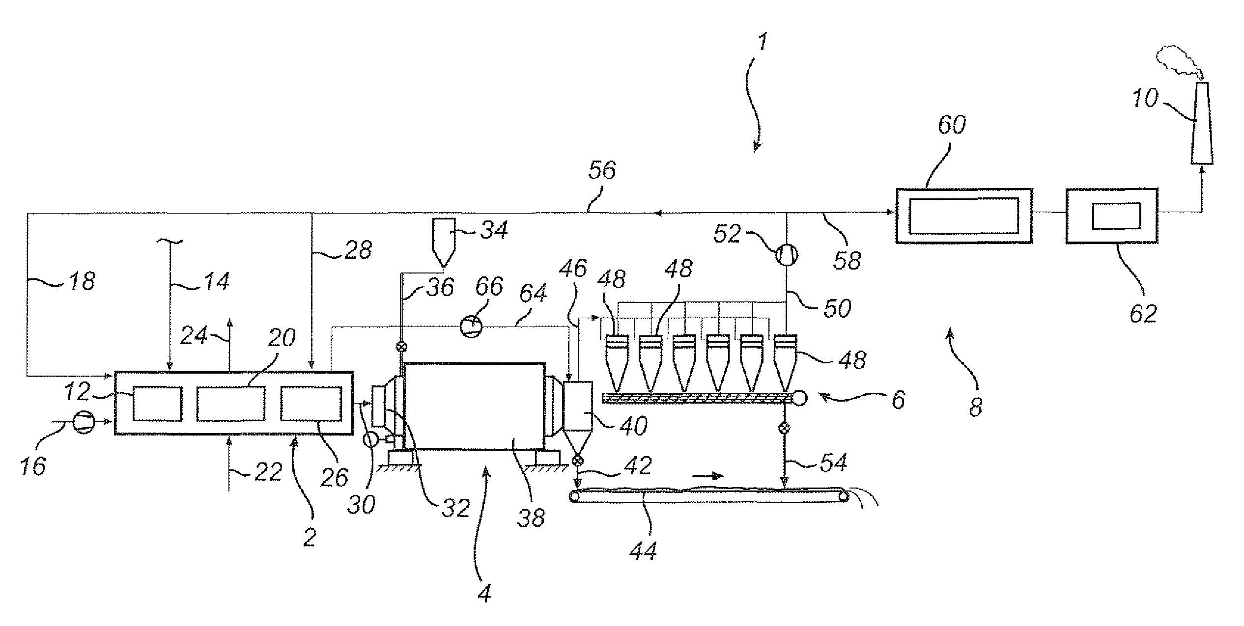
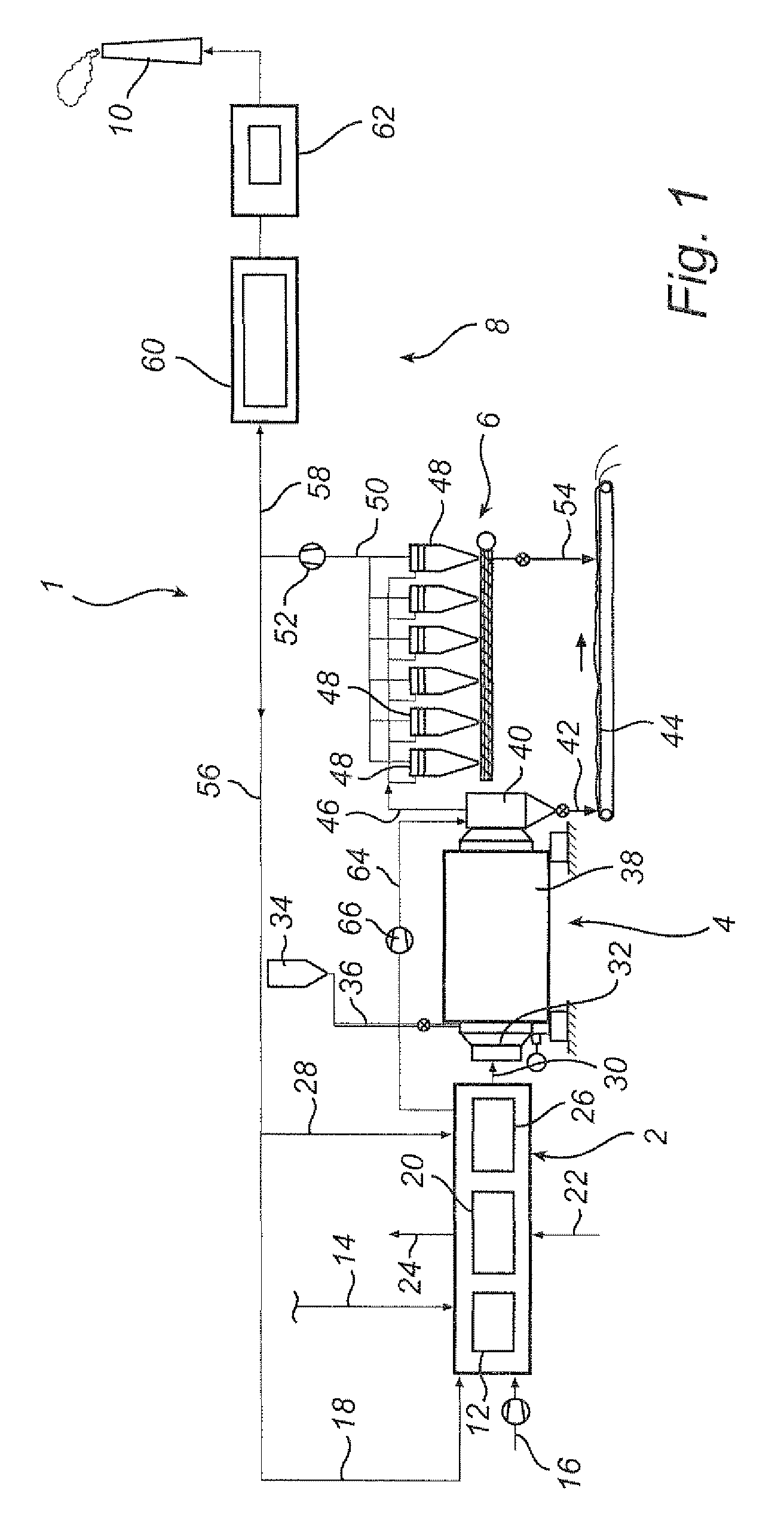
[0029]FIG. 1 illustrates a wood material drying plant 1 which is operative for drying wood material, such as wood chips and particulate wood material, prior to the further processing of the same for forming wood products, such as fuel pellets. The main components of the drying plant 1 are a heater 2, which is operative for providing a hot drying gas, and a rotary dryer 4, which is operative for bringing the hot drying gas into contact with the wood material to dry the latter, and for separating the major portion of the dried wood material from the spent drying gas. The wood material drying plant 1 further comprises a wood particle separating unit 6, which is operative for separating entrained wood particles from the spent drying gas downstream of the rotary dryer 4, and a gas cleaning system 8, which is operative for cleaning the spent drying gas, such that the spent drying gas may be admitted to the atmosphere via a stack 10.

[0030]The heater 2 comprises a burner 12 in which a fuel,...


PUM


Abstract

A wood material drying plant including a heater for generating a hot drying gas, a rotary dryer for bringing the hot drying gas into contact with the wood material to be dried, a wood particle separating unit being operative for separating entrained wood particles from the spent drying gas, and a gas cleaning system for removing pollutants from the spent drying gas. The wood material drying plant is provided with a heating gas duct which is operative for forwarding a gas portion to a mixing position located between the rotating drum of the rotary dryer and the wood particle separating unit, said gas portion having a higher temperature than the spent drying gas, and for mixing said gas portion with said spent drying gas, such that the temperature of the spent drying gas is increased.

Description

RELATED APPLICATIONS[0001]This application claims priority to Swedish patent application 0950639-5 filed on Sep. 7, 2009, the entirety of which is incorporated by reference.FIELD OF THE INVENTION[0002]The present invention relates to a wood material drying plant being operative for drying a wood material and comprising a heater for generating a hot drying gas, a rotary dryer for bringing, in a rotating drum thereof, the hot drying gas into contact with the wood material to be dried, a wood particle separating unit being operative for separating entrained wood particles from the spent drying gas, and a gas cleaning system for removing pollutants from the spent drying gas.[0003]The present invention further relates to a method of controlling the operation of a wood material drying plant.BACKGROUND OF THE INVENTION[0004]In the production of dried wood products, including, for example, pellets, also referred to as fuel pellets, a wood material, such as wood chips, wood saw dust etc., is...

Claims


Application Information

Patent Timeline
IPC IPC(8): F26B3/02F26B11/02
CPCF26B11/04F26B17/107F26B2200/24F26B21/10F26B25/007F26B21/04B01D53/002F26B25/005
Inventor LARSSON, OLALINDAHL, PETERBOHMAN, CRISTIAN
Owner ANDRITZ TECH & ASSET MANAGEMENT
Why Eureka
Try Eureka