Heat-assisted magnetic recording head with laser diode fixed to slider

a laser diode and magnetic recording technology, applied in the direction of mounting head within the housing, semiconductor lasers, instruments, etc., can solve the problems of increasing the coercivity of the recording medium, reducing the thermal stability of the magnetization of magnetic fine particles, and difficult to perform data recording with existing magnetic recording heads

Active Publication Date: 2011-03-10
HEADWAY TECH INC
View PDF39 Cites 27 Cited by
  • Summary
  • Abstract
  • Description
  • Claims
  • Application Information

AI Technical Summary

Benefits of technology

[0015]It is an object of the present invention to provide a heat-assisted magnetic recording head that makes it possible that, while using an edge-emitting laser diode as the light source for emitting light to be used for generating near-field light, alignment of the las...

Problems solved by technology

Making the magnetic fine particles smaller, however, causes the problem that the magnetic fine particles drop in the thermal stability of magnetization.
However, increasing the anisotropic energy of the magnetic fine particles leads to an increase in coercivity of the recording medium, and this makes it difficult to perform data recording with existing magnetic heads.
This causes the problem of increasing energy loss of the light in the path.
The second technique, however, has the following problem.
If the optical axis of the laser light emitted from the emission part tilts with respect to the optical axis of the waveguide, the laser light may fail to be delivered to the plasmon antenna with sufficient intensity.
When the laser diode is to be arranged so that the longitudinal direction of the laser diode is perpendicular to the end face of the slider where the in...

Method used


Image

  • Heat-assisted magnetic recording head with laser diode fixed to slider
  • Heat-assisted magnetic recording head with laser diode fixed to slider
  • Heat-assisted magnetic recording head with laser diode fixed to slider

Examples


first embodiment

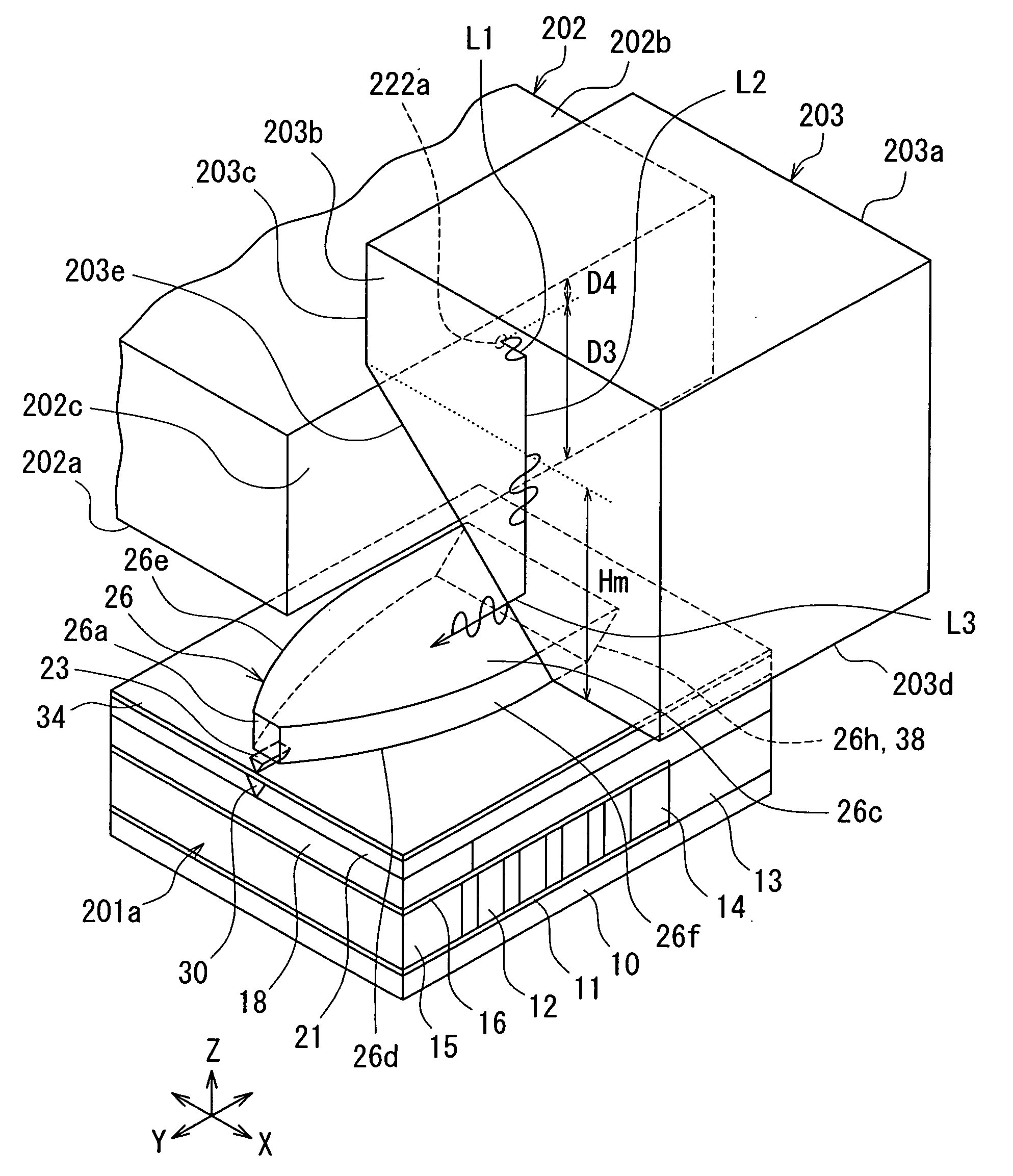
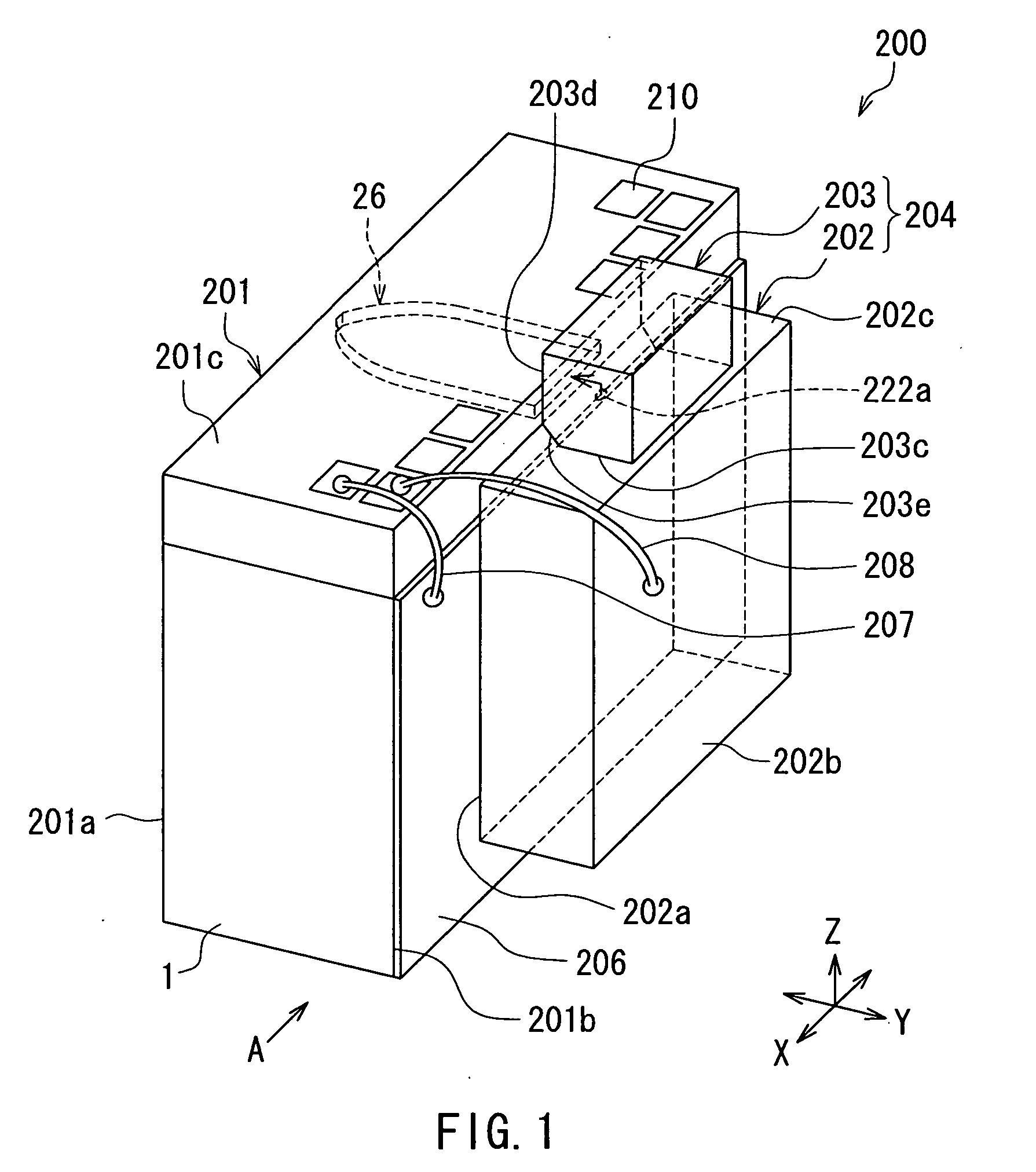
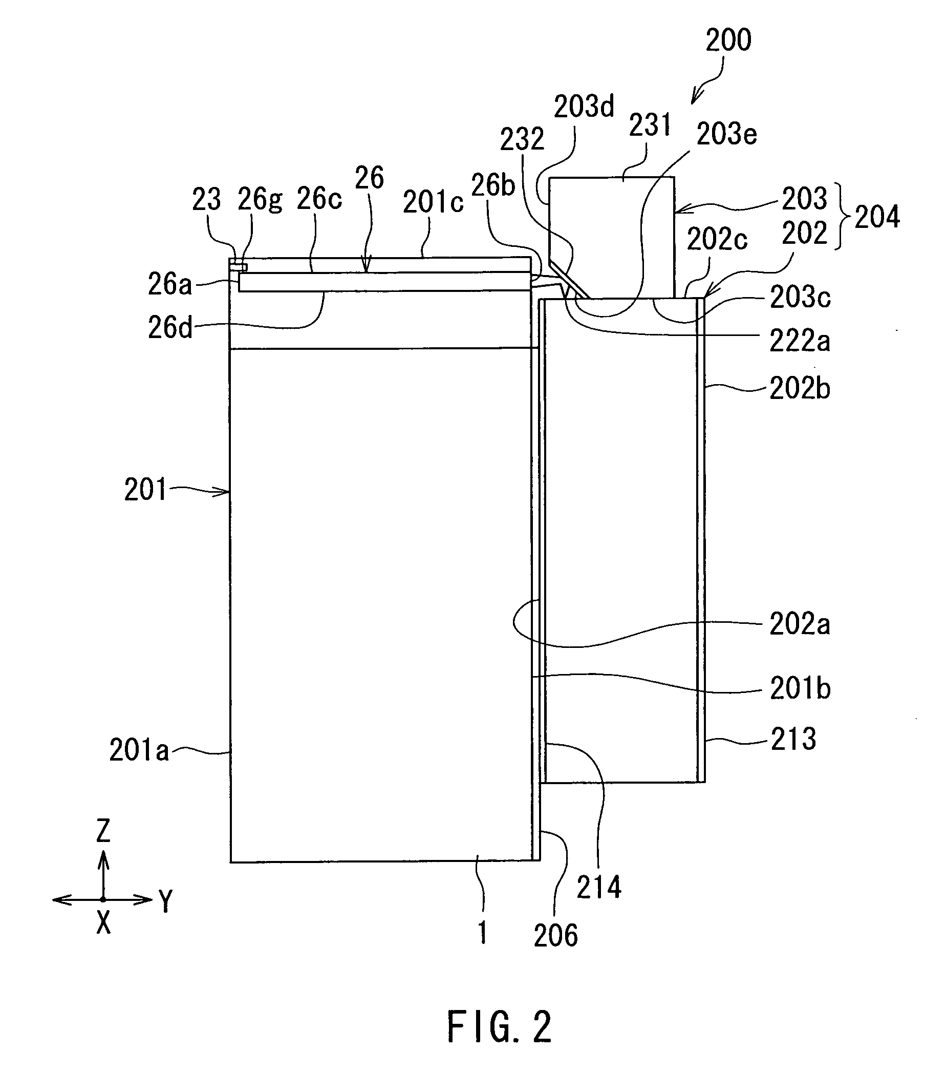
[0075]Preferred embodiments of the present invention will now be described in detail with reference to the drawings. Reference is first made to FIG. 1 and FIG. 2 to describe a heat-assisted magnetic recording head and a magnetic disk drive according to a first embodiment of the invention. FIG. 1 is a perspective view of the heat-assisted magnetic recording head according to the present embodiment. FIG. 2 is a side view of the heat-assisted magnetic recording head as viewed from the direction A of FIG. 1.

[0076]The magnetic disk drive of the present embodiment incorporates the heat-assisted magnetic recording head 200 according to the present embodiment. The heat-assisted magnetic recording head 200 is supported by a not-shown suspension and is disposed to face a circular-plate-shaped recording medium (magnetic disk) that is driven to rotate. In FIG. 1 and FIG. 2, the X direction is a direction across the tracks of the recording medium, the Y direction is a direction perpendicular to ...

modification example

[0153]A modification example of the present embodiment will now be described. FIG. 19 is a plan view showing a part of the waveguide 26 and the near-field light generating element 23 of the modification example. FIG. 20 is a perspective view of the near-field light generating element 23 shown in FIG. 19. In the near-field light generating element 23 of the modification example, the side surfaces 23d and 23e have their respective portions that decrease in distance from each other in the track width direction with decreasing distance to the medium facing surface 201a. The corner portion between the side surface 23d and the second end face 23b and the corner portion between the side surface 23e and the second end face 23b are both rounded. In this modification example, in particular, the side surfaces 23d and 23e excluding the above-mentioned two corner portions decrease in distance from each other in the track width direction with decreasing distance to the medium facing surface 201a....

second embodiment

[0161]A heat-assisted magnetic recording head according to a second embodiment of the invention will now be described with reference to FIG. 21 to FIG. 25. FIG. 21 is a perspective view of the heat-assisted magnetic recording head according to the present embodiment. FIG. 22 is a perspective view of the main part of the heat-assisted magnetic recording head shown in FIG. 21. FIG. 23 is a cross-sectional view showing the configuration of the slider of the present embodiment. FIG. 24 is a front view showing the medium facing surface of the slider of the present embodiment. FIG. 25 is a perspective view showing the near-field light generating element and its vicinity in the heat-assisted magnetic recording head according to the present embodiment.

[0162]In the present embodiment, the laser diode 202 is fixed to the slider 201 by bonding the p-electrode 214 (see FIG. 3) to the top surface 201c of the slider 201 such that the mounting surface 202a faces the top surface 201c and the emitti...


PUM


Abstract

A heat-assisted magnetic recording head includes a slider, an edge-emitting laser diode fixed to the slider, and an external mirror provided outside the slider. The slider includes a magnetic pole, a waveguide, and a near-field light generating element. The laser diode includes: an emitting end face that lies at an end in a direction parallel to the plane of an active layer and includes a laser-light emission part; and a mounting surface that lies at an end in a direction perpendicular to the plane of the active layer and faces the slider. The external mirror includes: a first reference surface that is parallel to the emitting end face and faces the emitting end face; a second reference surface that is parallel to the mounting surface and faces toward the same direction as the mounting surface does; and a reflecting surface that connects the first and second reference surfaces to each other and reflects the laser light emitted from the emission part toward the waveguide.

Description

BACKGROUND OF THE INVENTION[0001]1. Field of the Invention[0002]The present invention relates to a heat-assisted magnetic recording head for use in heat-assisted magnetic recording where a recording medium is irradiated with near-field light to lower the coercivity of the recording medium for data recording.[0003]2. Description of the Related Art[0004]Recently, magnetic recording devices such as a magnetic disk drive have been improved in recording density, and thin-film magnetic heads and magnetic recording media of improved performance have been demanded accordingly. Among the thin-film magnetic heads, a composite thin-film magnetic head has been used widely. The composite thin-film magnetic head has such a structure that a reproducing head including a magnetoresistive element (hereinafter, also referred to as MR element) for reading and a recording head including an induction-type electromagnetic transducer for writing are stacked on a substrate. In a magnetic disk drive, the thi...

Claims


Application Information

Patent Timeline
IPC IPC(8): G11B5/02H01L21/50H01S5/00G11B21/16
CPCG11B5/314G11B5/6088G11B2005/001G11B2005/0021G11B5/105H01S5/02272H01S5/0228H01S5/02292H01S5/0224H01S5/0225H01S5/02255H01S5/0234H01S5/0237
Inventor SASAKI, YOSHITAKAITO, HIROYUKITANEMURA, SHIGEKIARAKI, HIRONORI
Owner HEADWAY TECH INC
Why Eureka
Try Eureka