
Detector, physical quantity measuring device, and electronic apparatus

Active Publication Date: 2011-03-17
SEIKO EPSON CORP
View PDF5 Cites 13 Cited by
  • Summary
  • Abstract
  • Description
  • Claims
  • Application Information

AI Technical Summary

Benefits of technology

[0010]An advantage of some aspects of the invention is that it provides a detector which sets the output load capacity equal and which can improve the S / N ratio at a low cost, a physical quantity measuring device, and an electronic apparatus when performing an output operation with a plurality of kinds of sensitivities.

Problems solved by technology

In this case, since noise increases, it is not possible to improve the S / N ratio.
In this case, there is a problem that the costs increase in order to maintain the detection accuracy.
In the devices disclosed in JP-A-2000-88578, JP-A-2006-292469, JP-A-2002-267452, and JP-A-11-282502, however, the power consumption increases even if the gain is simply changed, because the signal is amplified using a resistance element instead of a switched capacitor circuit.
As a result, it is not possible to obtain a high-sensitivity output because noise is also amplified, even though the high-sensitivity output is needed.
As a result, there is a problem in that signal processing at the subsequent stage becomes complicated and the usability becomes worse accordingly.
In addition, in the devices disclosed in JP-A-2000-88578, JP-A-2006-292469, JP-A-2002-267452, JP-A-11-282502, and JP-A-7-218270, it is not possible to make the output load capacity equal for every output when outputting a plurality of kinds of outputs.

Method used


Image

  • Detector, physical quantity measuring device, and electronic apparatus
  • Detector, physical quantity measuring device, and electronic apparatus
  • Detector, physical quantity measuring device, and electronic apparatus

Examples


Embodiment Construction

[0057]Hereinafter, embodiments of the invention will be described in detail with reference to the accompanying drawings. In addition, the embodiments described below are not intended to limit the contents of the invention defined by the appended claims. In addition, all of the configurations described below are not necessarily essential components which are required to achieve the advantages of the invention.

1. Sensor Circuit

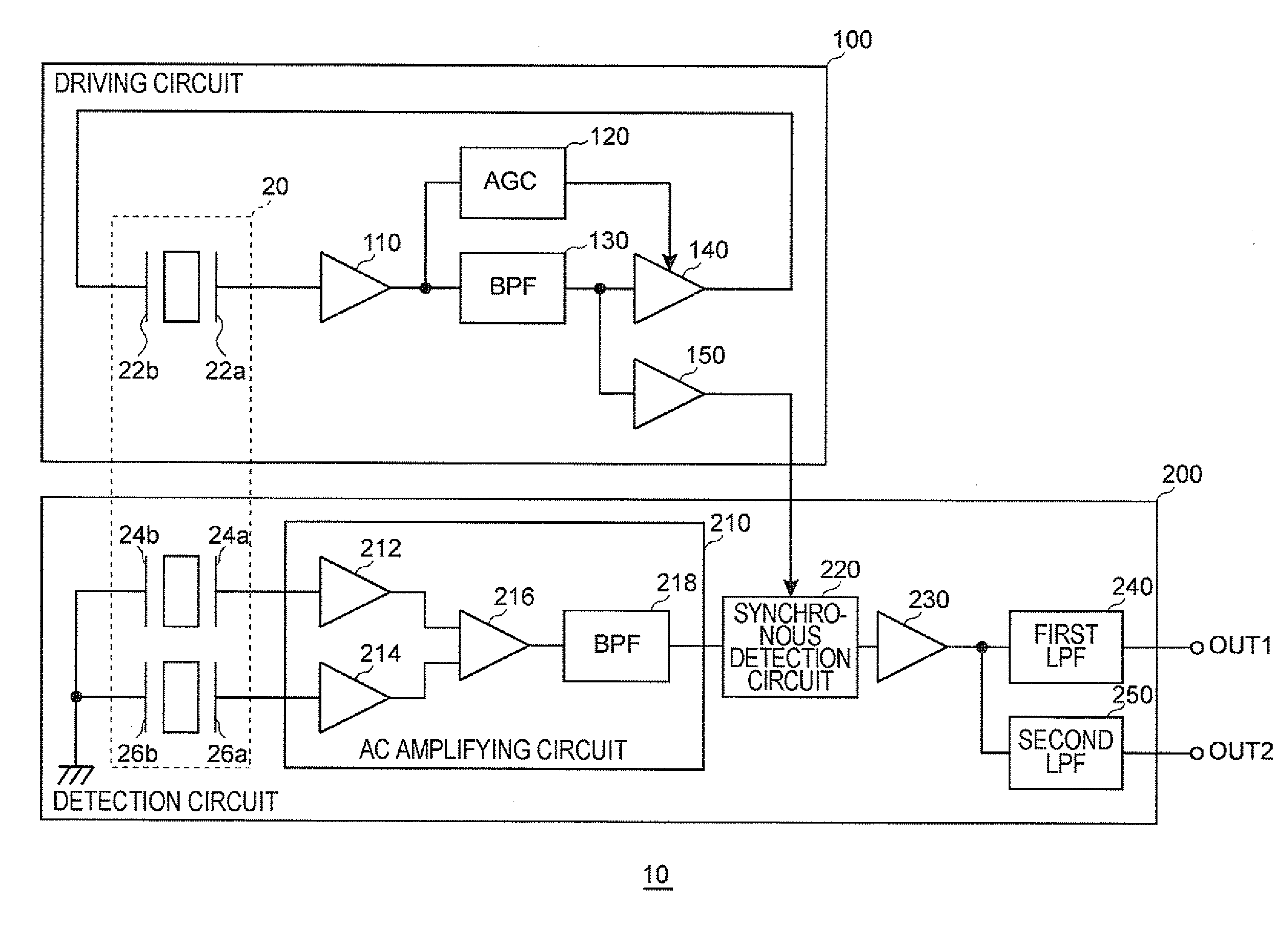
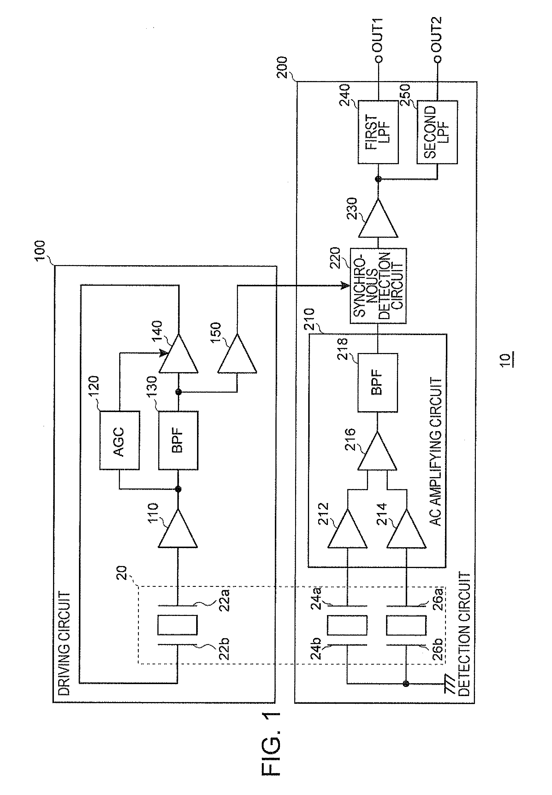
[0058]FIG. 1 is shows an example of the configuration of a sensor circuit in an embodiment of the invention. Moreover, this circuit configuration is an example and, for example, the detailed configuration of the circuit may be changed.

[0059]A sensor circuit 10 is a physical quantity measuring device which measures angular velocity as a physical quantity to be measured. The sensor circuit 10 includes a driving circuit (driving device) 100 and a detection circuit (detector) 200. The sensor circuit 10 is formed of a piezoelectric material, and includes a vibrating ...


PUM


Abstract

A detector that detects a detection signal corresponding to a driving vibration, which excites a vibrator in an oscillation loop, and a physical quantity to be measured, includes: an amplifying circuit that amplifies a signal corresponding to the driving vibration and the physical quantity; a synchronous detection circuit that detects the amplified signal of the amplifying circuit in synchronization with an oscillation signal in the oscillation loop; an impedance conversion circuit that converts an output impedance of the synchronous detection circuit; a first low pass filter to which an output signal of the impedance conversion circuit is supplied and which outputs a first detection signal; and a second low pass filter to which the output signal of the impedance conversion circuit is supplied and which outputs a second detection signal.

Description

[0001]The entire disclosure of Japanese Patent Application No. 2009-210175, filed Sep. 11, 2009 is expressly incorporated by reference herein.BACKGROUND[0002]1. Technical Field[0003]The invention relates to a detector, a physical quantity measuring device, and an electronic apparatus.[0004]2. Related Art[0005]A sensor circuit which measures a physical quantity, such as angular velocity, has been mounted in a vehicle, an electronic apparatus, and the like in order to detect vibration caused by vehicle movement, hand shaking, and the like. In recent years, as the sensor circuit is used for increasingly varied applications, there is a case where a plurality of outputs is output from a sensor circuit and the physical quantity is measured using each output according to their purposes, for example.[0006]Various sensor circuits which output a plurality of outputs have been proposed. For example, JP-A-2000-88578 discloses an angular velocity sensor that includes two detection means, which d...

Claims


Application Information

Patent Timeline
IPC IPC(8): G01C19/56G01C19/5614G01C19/5621G01C19/5776
CPCH03H19/004G01C19/56
Inventor YOSHIDA, NAOKI
Owner SEIKO EPSON CORP
Learn More