Automated transport system

a technology of automatic transportation and transport system, applied in the direction of transportation items, electric/hybrid propulsion, electric devices, etc., can solve the problems of not necessarily good ideas and hard to escape, and achieve the effects of low cost, high efficiency, and high efficiency

Inactive Publication Date: 2011-03-17
AUTRAN CORP
View PDF13 Cites 30 Cited by
  • Summary
  • Abstract
  • Description
  • Claims
  • Application Information

AI Technical Summary

Benefits of technology

[0028]Further features of the second embodiment relate to a carrier drive train designed to be highly efficient in operation, versatile, low in cost and reliable. The drive train includes an AC induction motor that can be powered from the grid and a transmission between the induction motor and the main drive wheel. In an illustrated embodiment, the transmission includes two planetary gear trains that are coupled in series relation. A sun gear of each train is connected to a caliper brake to control drive from a planet-carrier to a ring gear. Through control of the caliper brakes and through selective lock-ups of the two gear trains, substantially constant carrier speeds of about 45 MPH, about 63 MPH and about 88 MPH are developed with drive from the induction motor that is operated with high efficiency at near rated speed.
[0029]The drive train also includes a DC motor / generator connected to batteries and usable alone to drive main wheel in the event of failure of power from the grid. An important feature is that the DC motor / generator is also usable to supply torque to the main drive wheel during time intervals of acceleration of the carrier and to provide regenerative braking during time intervals of deceleration of the main wheel. In the event of an AC power failure, the DC motor / generator is usable to move a carrier to a station ahead, which can be done at a relatively low speed so that the motor / generator can be of limited rated capacity for continuous operation and of relatively smaller size and cost. During time intervals of acceleration and deceleration, which can be of relatively short duration, the DC motor / generator can be safely operated at power levels much greater that its rated capacity.
[0030]Use of the DC motor / generator during accelerations and decelerations complements a drive / braking control system in which control is exercised through control of torque applied to one element of a planetary gear train. Such control systems are highly advantageous when used for control of the speed of carriers powered from induction motors, carrying different types of loads and following one-another along guideways. However, there are problems in attempting to use such gear trains used solely for acceleration of a carrier from zero speed to a maximum. The use of the DC motor / generator minimizes such problems. The operation of the planetary gear trains is such that the output ring gear can be accelerated from zero velocity to a maximum velocity through braking of the sun gear from a maximum velocity to a zero velocity. If the output torque is constant, the braking power loss (proportional to the product of torque and angular velocity) is at a maximum at the start and decreases linearly to zero when the output ring gear is rotating at its maximum angular velocity. The braking power loss could thus be very large if acceleration of the carrier is obtained solely through use of the gear trains. However, when the DC motor / generator is operated to supply a large portion of the torque required to accelerate to the maximum velocity, the power loss from braking of sun gears can be reduced to a reasonable value. The operation of the planetary gear trains is also such that power losses from braking of sun gears are not a significant problem when control of braking occurs at near maximum carrier speed, as will normally be the case. When a carrier is powered by an induction motor, its speed will decrease from a maximum value in proportion to load but in normal circumstances only as a relatively small fraction of the maximum speed. For example, a carrier that carries no load may move at say 86 MPH while a carrier that carries an SUV having a high CD (aerodynamic drag coefficient) may move at say 83 MPH. If a series of carriers are moving along a guideway, some carrying SUVs and others that are unloaded or that have smaller CD's, the sun gears of those carrying SUVs will be braked to a full extent to a zero velocity, with no loss from braking of the sun gears. At the same time, it will be necessary reduce braking of sun gears to allow such other carriers to slow down to 83 MPH, but the associated losses from braking of sun gears will be quite small in relative terms.
[0031]Another feature of the invention relates to a design of a platform onto which a car may be driven to be carried by a carrier to a desired destination. I consider the carrying of cars to be extremely important for four primary reasons. The first is safety. Drivers and other occupants of cars are much safer when in a car being carried on a dedicated guideway rather than operating on streets or highways. The second reason relates of avoidance of congestion. In many regions, guideways can be elevated and build along rights-of-way that are available or otherwise much less expensive than would be required to add new lanes of comparable carrying capacity. The third reason relates to minimizing the pollution and avoiding the burning of gasoline or diesel fuels which would otherwise occur with a car moving on streets or highways. The fourth reason relates to the eventual construction of a network that can carry passengers in cabins or cargo in containers or on pallets as well as cars on platforms. As soon as built, guideways that can carry cars on platforms can be immediately profitable, can lead to expansions and interconnections into networks to which passenger and cargo-carrying capabilities can be readily added.
[0032]An illustrated platform is designed for fast and reliable loading of cars thereon and to be low in cost. The platform includes a pair of stop elements that are at the forward end of a platform and that have upright positions in which they are engage-able by front bumper portions of a car. A pair of wheel chocks are then lifted out of pockets in the platform and moved ahead to engage behind the front wheels of a car. The car and platform are then moved to a destination unloading station at which the chocks are moved back into the pockets and at which the stop elements are swung forwardly and down, allowing the car to be driven onto the receiving end of an exit driveway. Then the stop elements are swung up and back the then down into receiving slots in the platform which then has a low profile and can be moved either directly to a loading position in a loading station or to a queue of a loading station to await movement to loading position.
[0033]Further features of the invention relate to a wheel that is for use as a driven wheel in moving a carrier and that includes magnetic means for obtaining increased traction. The use of a steel wheel moving on a steel rail has important advantages as to efficiency and as to maintenance and costs but has limitations with respect to traction. Traction can be increased though the use of wheels engaged with undersides of auxiliary rails, as I have described herein. The use of magnetic means to increase traction is an attractive possibility, either for use alone or as a means to enhance the increased traction obtained through the use of the upper guide rails.

Problems solved by technology

The idea of obtaining stability through support wheels that are spaced longitudinally and laterally is so pervasive that it is hard to escape from.
However, I find that the idea is not necessarily a good idea when a vehicle can be supported in a guideway or the like and when it is realized that means other than spacings of support wheels can be used to obtain stability.

Method used


Image

  • Automated transport system
  • Automated transport system
  • Automated transport system

Examples


Embodiment Construction

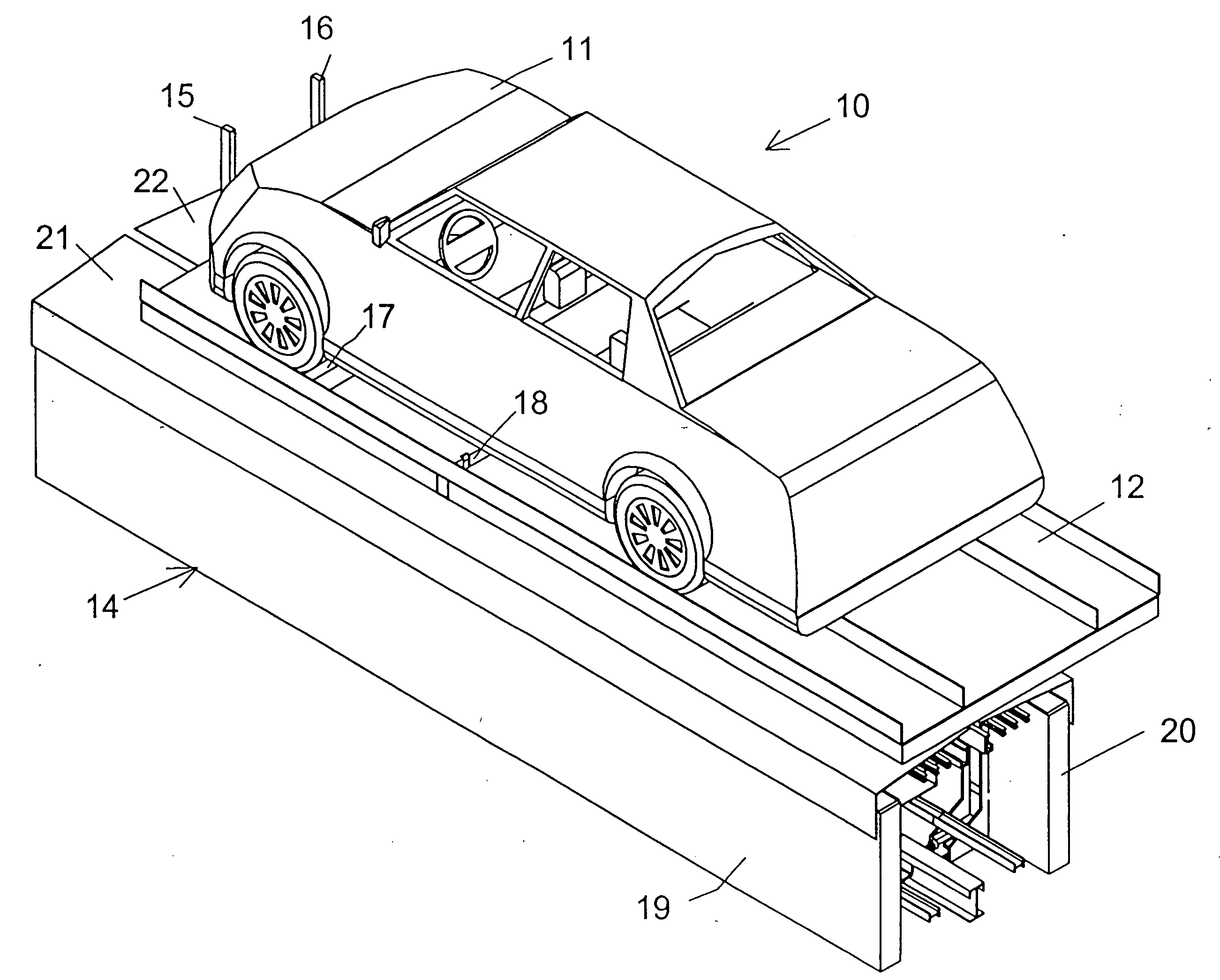
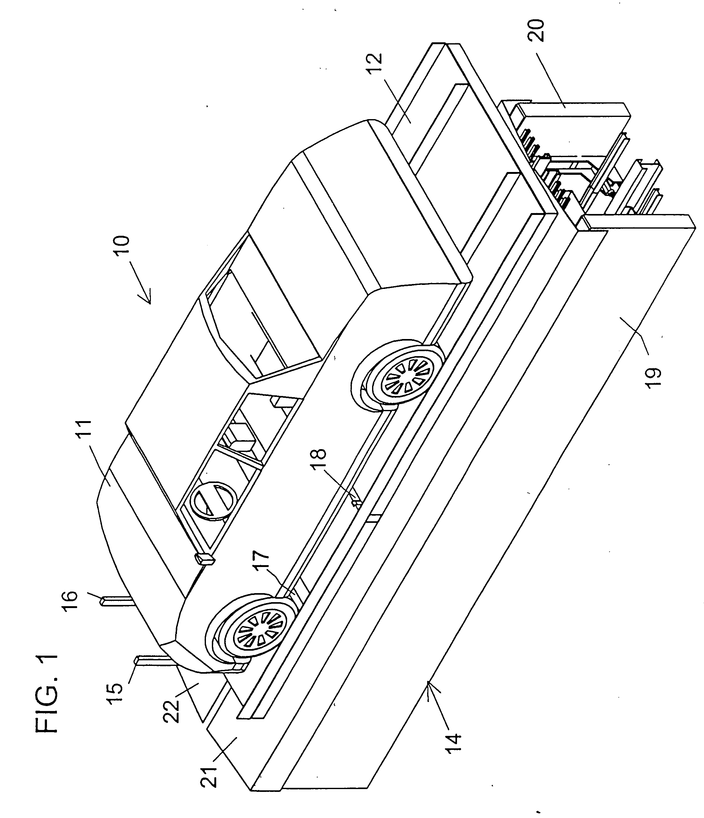
[0070]Reference numeral 10 generally designates one form of transportation system constructed in accordance with the invention, portions of which are shown in FIG. 1. The system 10 is particularly designed for expansion and to eventually form a wide-scale network for automated carrying of various types of loads by carriers moving in guideways. The carrying of a car 11 is shown. The system 10 can also be used to carry passengers, freight and other loads.

[0071]The car 11 is shown being carried on a pallet or platform 12 above a short section of a guideway 14. Guideway 14 may be of any desired length and may extend forwardly to a divergent Y-junction at which carriers may be steered to either of two guideways. The guideway 14 may also extend rearwardly to the end of a convergent Y-junction that receives carriers entering from either of two guideways.

[0072]The platform 12 is similar to, but different from, that disclosed in my U.S. Pat. No. 6,237,500 issued May 29, 2001. Platform 12 inc...


PUM


Abstract

A single main steel wheel rides on a single main steel rail of a guideway to support and drive a carrier and to facilitate steering and provide a simplified, more compact and less costly construction. The carrier can support a car through a platform having elements and chocks for locking contact with a front bumper and front wheels of the car Auxiliary wheels and rails cooperate to cause nearly all weight to be carried through the single main wheel. Traction is increased when necessary through application of increased upward forces to undersides of auxiliary rails and/or through developing magnetic forces between the steel wheel and steel rail. An AC induction motor is a main source of drive power. Acceleration and braking are assisted through epicyclic gearing, braking means and a DC motor/generator that is connected to a battery and that drives the carrier if supply of AC fails.

Description

[0001]A claim is made for the priority benefits of Provisional Application No. 61 / 205,777, entitled “AUTOMATED TRANSPORT SYSTEM”, filed Feb. 4, 2009 and of Provisional Application No. 61 / 276,370, entitled “AUTOMATED TRANSPORT SYSTEM”, filed Sep. 11, 2009.BACKGROUND OF THE INVENTION[0002]This invention relates to improvements upon prior automated transport systems, particularly those disclosed in my U.S. Pat. Nos. 5,590,603, 5,590,604, 5,598,783, 5,706,735, 5,979,334, 6,082,268, 6,237,500 and 6,622,635 and in references cited therein.SUMMARY OF THE INVENTION[0003]Important aspects of the invention relate to analyses of prior systems and the discovery and recognition of problems with and deficiencies with such systems. In the past, vehicles such as wagons, carriages and automobiles and cars or bogies of trains have commonly used four support wheels for support either directly from underlying ground or through roadways or rails. Sometimes only three wheels have been used. In such vehic...

Claims


Application Information

Patent Timeline
Patent Type & Authority Applications(United States)
IPC IPC(8): B61B13/04E01B25/10E01B25/12G06F19/00B60L11/00B60L13/00B60L9/00F16H57/10B60P3/07B60P3/073B60P3/077
CPCB60L5/36B60L2200/26B60L9/08B60L9/28B60L11/1803B60L11/1805B60L15/38B60L2200/44B60L2220/12B60L2260/32B60M1/32B61B13/00E01B25/10Y02T10/7005Y02T30/30B60L7/12Y02P90/60B60L50/51B60L50/52Y02T30/00Y02T10/70
Inventor LUND, VAN METRE
Owner AUTRAN CORP
Why Eureka
Try Eureka