Laser radar by taking liquid crystal device as light beam deflection device

A technology of liquid crystal devices and beam deflection, which is applied in instruments, optics, nonlinear optics, etc., can solve the problems of low diffraction efficiency and achieve low cost, good stability, and high reliability

Pending Publication Date: 2020-02-14
SHENZHEN AV DISPLAY
View PDF0 Cites 0 Cited by
  • Summary
  • Abstract
  • Description
  • Claims
  • Application Information

AI Technical Summary

Problems solved by technology

[0003] The technical problem to be solved by the present invention is: use liquid crystal device as the element of optical phase control, the problem of low diffraction efficiency

Method used


Image

  • Laser radar by taking liquid crystal device as light beam deflection device
  • Laser radar by taking liquid crystal device as light beam deflection device

Examples


Embodiment 1

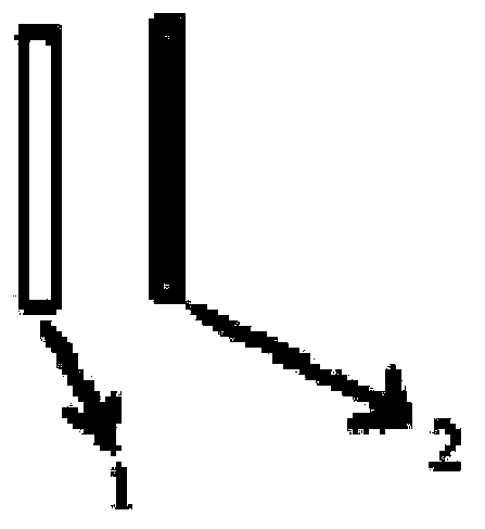
[0028] The first deflection unit includes a first liquid crystal phase retarder 1 and a first polarization grating 2, the first liquid crystal phase retarder is used to delay the incident light, and its phase retardation is a quarter wave plate, To convert the incident linearly polarized light into circularly polarized light or maintain linearly polarized light, the first polarization grating can deflect the incident light by an angle θ, where θ is greater than or equal to zero.

[0029] Thus, the first liquid crystal phase retarder 1 acts as a quarter-wave plate, which can convert linearly polarized light into circularly polarized light, and does not change the polarization state of the light when a high voltage is applied. The polarization grating 2 can realize the following functions: when the incident light is linearly polarized, the angle and polarization state of the light will not be changed; When the grating is used, the left-handed circularly polarized light and the r...

Embodiment 2

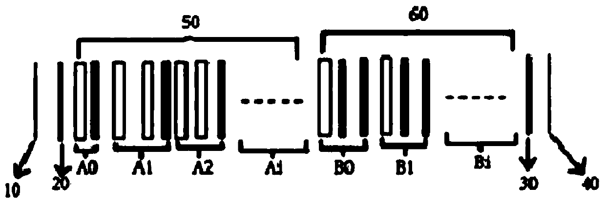
[0031] There are multiple second deflection units, and the multiple second deflection units are arranged in a row, and each deflection unit deflects or does not deflect the angle of light.

[0032] Thus, the total retardation of one or two or more liquid crystal phase retarders 1 reaches the effect of a half-wave plate, which can convert left (right) circularly polarized light into right (left) circularly polarized light, or one of them can add When the voltage is high, the circular (linear) polarized light can be converted into linear (circular) polarized light, or the polarization state of the light can not be changed when the voltage is applied at the same time. The combination of i systems can realize angular deflection from 0° to i*θ (i=1, 2, 3 . . . ).

Embodiment 3

[0034] A second deflection system 60 is included, the second deflection system 60 is located at the rear end of the first deflection system 50, and the second deflection system 60 is used to adjust the deflected light of the first deflection system 50 to a maximum deflection angle.

[0035] Thus, the second deflection system 60 can deflect the incident light by 2*i*θ (θ is the deflection angle of a single deflection grating, i=0,1,2... depends on the number of subsystems Bi ). If the polarization state of light before the second deflection system 60 is circularly polarized light, when the liquid crystal device in B1 works at high voltage, the polarization state of the light does not change after passing through the liquid crystal device, and it is still circularly polarized light. After the grating, the light is deflected by 2*θ. If the liquid crystal devices with m subsystems in the second deflection system work under high voltage (without changing the polarization state of ...


PUM


Abstract

The invention discloses laser radar by taking a liquid crystal device as a light beam deflection device. The laser radar comprises a first angle deflection system, the first angle deflection system comprises a first deflection unit and at least one second deflection unit; the first deflection unit deflects the incident light to obtain deflected light; and each second deflection unit comprises a second polarization grating and at least one second liquid crystal phase retarder, the at least one second liquid crystal phase retarder is used for delaying the deflected light to enable the total retardation of the deflected light to reach a half-wave plate, and the at least one second polarization grating is used for deflecting the deflected light again. The liquid crystal phase retarder and thepolarization grating are applied to a laser radar system, high-efficiency operation of the system is achieved, reliability is high, stability is good, cost is low, and large-scale commercialization can be achieved.

Description

technical field [0001] The invention relates to the technical field of laser radar, in particular to a laser radar using a liquid crystal device as a light beam deflection device. Background technique [0002] Lidar is a system that emits laser beams to detect characteristic quantities such as the position and speed of targets, and is widely used in the field of laser detection. In order to be suitable for two-dimensional or three-dimensional detection, the laser beam emitted by the lidar needs to be rotated. Optical phased array elements are usually used to control the wavefront phase of the laser beam, so as to control the direction of the emitted beam. With the advancement of liquid crystal display technology, liquid crystal devices are used as optical phase control elements, but this method has the disadvantages of high etching precision of liquid crystal substrate electrodes and low diffraction efficiency. Contents of the invention [0003] The technical problem to ...

Claims


Application Information

Patent Timeline
IPC IPC(8): G02F1/13G02F1/29G01S7/481
CPCG01S7/481G02F1/1313G02F1/29G02F1/293
Inventor 熊培成吴梓荣陈嵘
Owner SHENZHEN AV DISPLAY
Why Eureka
Try Eureka