Offshore Casing Drilling Method

Inactive Publication Date: 2011-03-17
SCHLUMBERGER TECH CORP
View PDF5 Cites 12 Cited by
  • Summary
  • Abstract
  • Description
  • Claims
  • Application Information

AI Technical Summary

Benefits of technology

After reaching the total depth, the operator retrieves the drill bit assembly from the casing string in one or more methods. That can be done by lowering a string of drill pipe through the casing, running a wireline into the casing, or by pumping the drill bit assembly up through the casing string using reverse circulation. The operator then is free to cement the string of casing in the well. At least one plug will be typically pumped down the casing string to latch onto a lower portion of the casing string and prevent backflow of cement from the casing annulus back into the casing string.

Problems solved by technology

This depth may be just above a difficult zone.

Method used


Image

  • Offshore Casing Drilling Method
  • Offshore Casing Drilling Method
  • Offshore Casing Drilling Method

Examples


Embodiment Construction

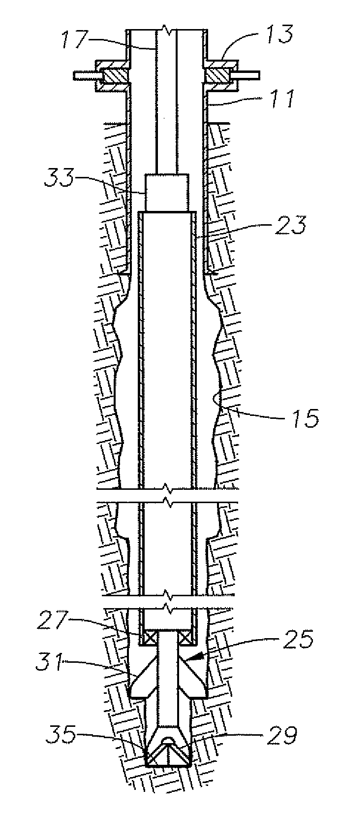
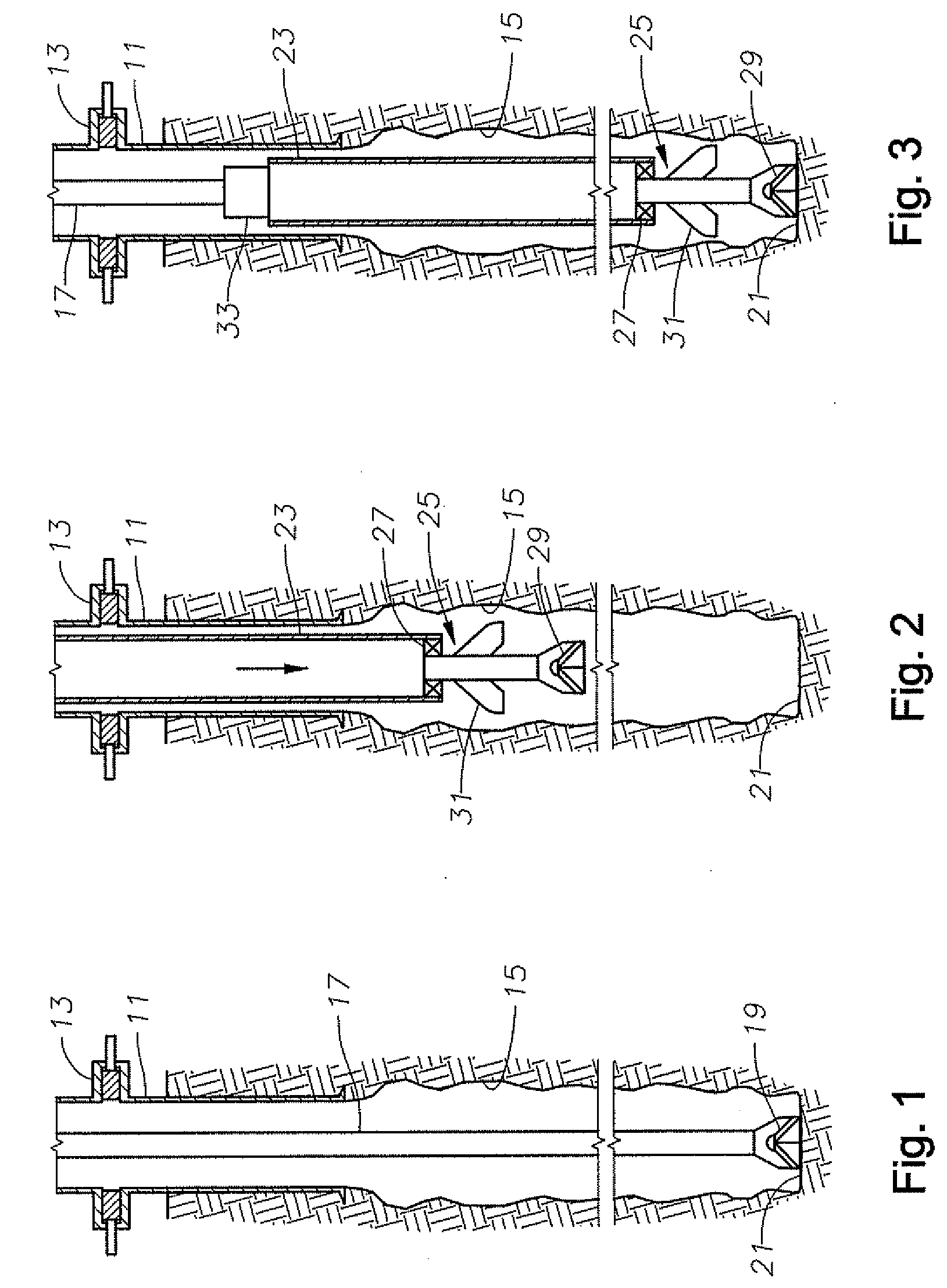
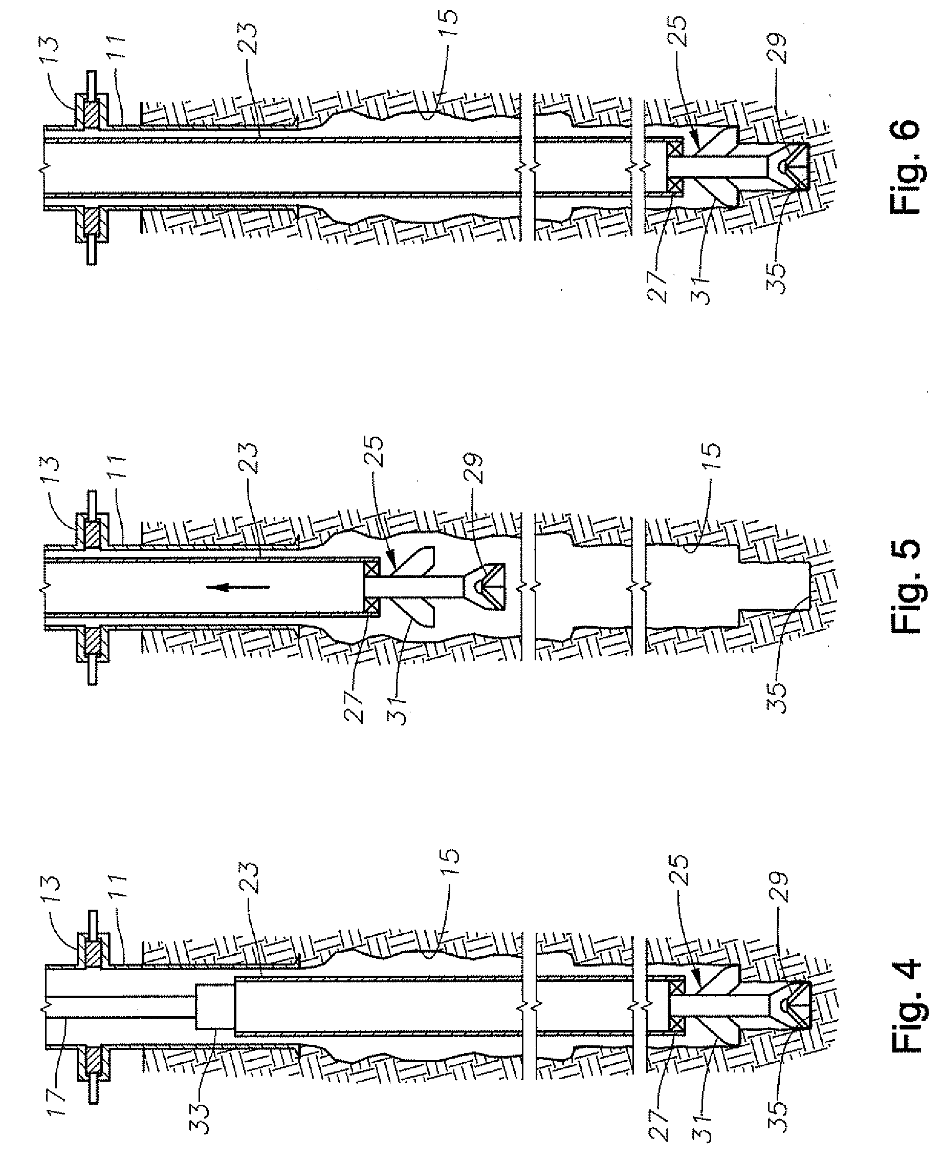
Referring to FIG. 1, an outer casing string 11 is shown cemented in an offshore well. Outer casing string 11 is schematically shown connected to a blowout preventer (BOP) 13. BOP 13 could be located subsea, but preferably is located above sea level. Outer casing string 11 could have a lower portion located below the mud line or sea floor and an upper portion that latches into the lower portion at the mud line or sea floor. The upper portion of outer casing string 11 serves as a riser to confine drilling fluid while drilling the well. BOP 13 has a number of elements for closure, including pipe rams, a full closure annular element, and shear rams.

An open hole section 15 of the well is illustrated as being drilled by a string of drill pipe 11 having a drill bit 19 on its lower end. The operator drills open hole section 15 conventionally by rotating drill pipe 17 and drill bit 19. The operator pumps drilling fluid down drill pipe 17, which flows back up open hole section 15 and outer ca...


PUM


Abstract

A method of casing drilling a portion of an offshore well includes running a casing string with a drill bit assembly attached to it into a previously drilled portion of the well. Before the drill bit assembly reaches bottom, the operator attaches drill pipe to the casing string and lowers the casing string on the drill pipe. When the drill bit is at bottom, an upper end of the casing string should be below the blowout preventer. The operator then performs casing drilling by rotating the drill pipe. When at a desired depth for the casing string, the operator pulls the drill pipe from the well and lifts the casing string up until its upper end is at the rig floor. The operator then runs the casing string back into the well but using casing in this instance. The operator then cements the casing string.

Description

BACKGROUND OF THE INVENTIONOffshore drilling normally takes place with either a floating drilling rig, a fixed platform, or a jackup drilling rig. A riser or some other type of conduit will extend from the seafloor to the drilling rig. The riser will have a blowout preventer (BOP) that is able to close around a drill string as well as to sever it. The BOP serves to prevent a dangerous blowout of the well in the event an unexpectedly high pressure earth formation is drilled into and overcomes the hydrostatic pressure of the drilling fluid. The BOP may be located subsea near the seafloor or it may be located above sea level at the drilling rig.Normally the operator drills the well with a string of drill pipe. Drill pipe comprises thick wall joints of pipe that are secured together to make up a string. The drill pipe is constructed so to allow the operator to frequently unscrew and screw the joints together. When the operator reaches a depth that he wishes to run casing, he pulls out t...

Claims


Application Information

Patent Timeline
Patent Type & Authority Applications(United States)
IPC IPC(8): E21B7/20E21B33/06E21B33/00
CPCE21B7/20
Inventor BOYLE, JOHN
Owner SCHLUMBERGER TECH CORP
Why Eureka
Try Eureka