
System of Controlling Fluid Flow

Inactive Publication Date: 2011-03-17
ADMON MISS YONA
View PDF27 Cites 8 Cited by
  • Summary
  • Abstract
  • Description
  • Claims
  • Application Information

AI Technical Summary

Benefits of technology

[0020]One advantage of the present invention is providing a remote controlled fluid valve which overcomes the above-mentioned and other drawbacks of the prior art.

Problems solved by technology

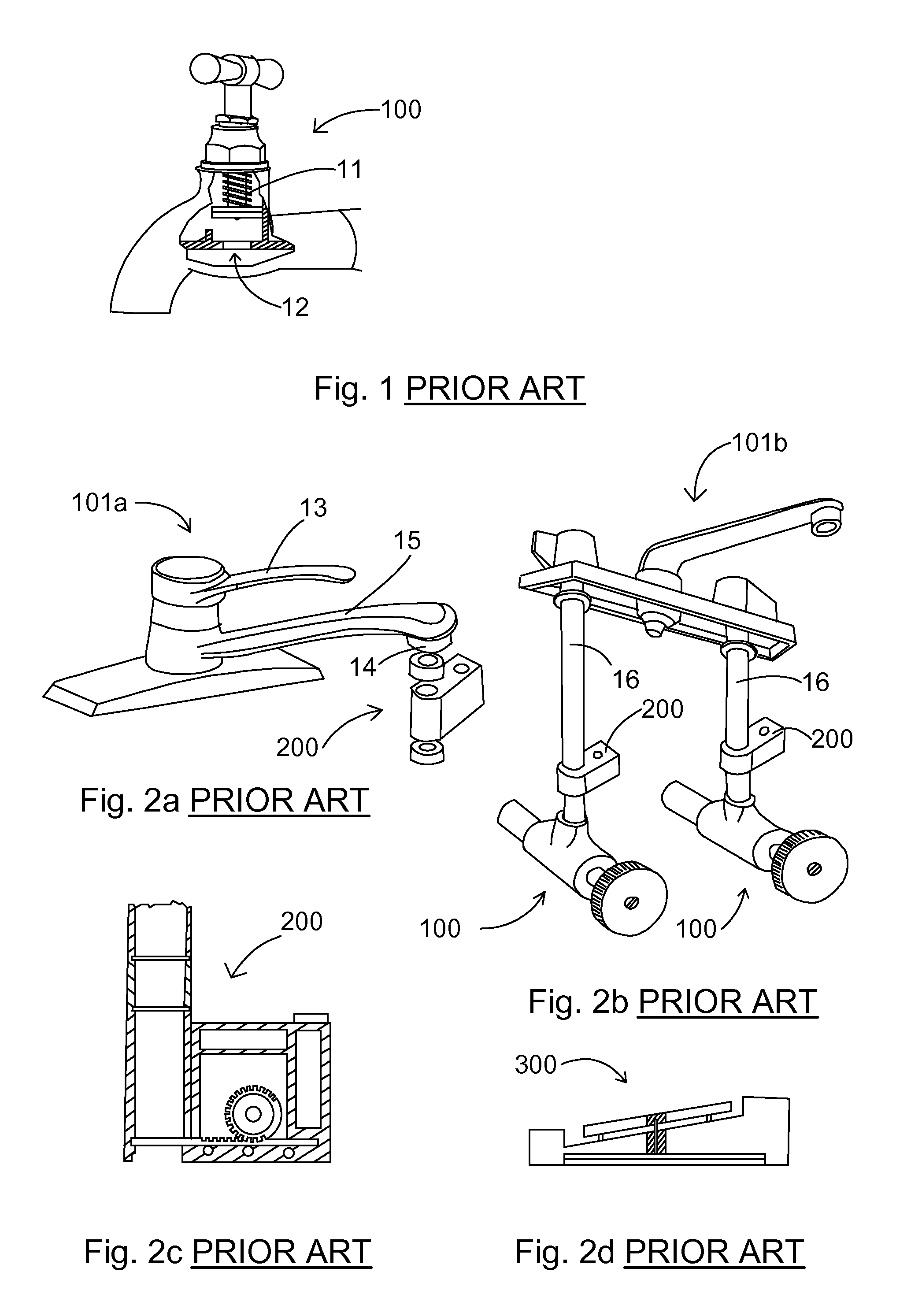
However, there are several drawbacks to use of a screw-down mechanism 11 and of lever-operated faucets, one example is the hygiene problem caused by the physical contact between users and levers in lavatories.
Such a device fails to meet the demand for continuous flow without the presence of a person, such as in the case of filling water containers, when the user wishes to start the flow of water, go do something else, and come back to stop the flow.
Another drawback is that due to the inconvenience of turning the lever or the screw on and off, some users avoid turning off a faucet during intermittent use.
This results in considerable waste of water.
Furthermore, some users may forget to turn off a faucet, which also results in significant waste of water.
In the event a potentially dangerous liquid is involved in the faucet operation, this could end in disaster.
The external shape of prior art valve assembly 200 is cubed, and when it connects to a supply line or to a faucet, it mostly protrudes from the flow line, and its corners pose a physical hazard, seeing as they could wound any person who runs into them in any way.

Method used


Image

  • System of Controlling Fluid Flow
  • System of Controlling Fluid Flow
  • System of Controlling Fluid Flow

Examples


Embodiment Construction

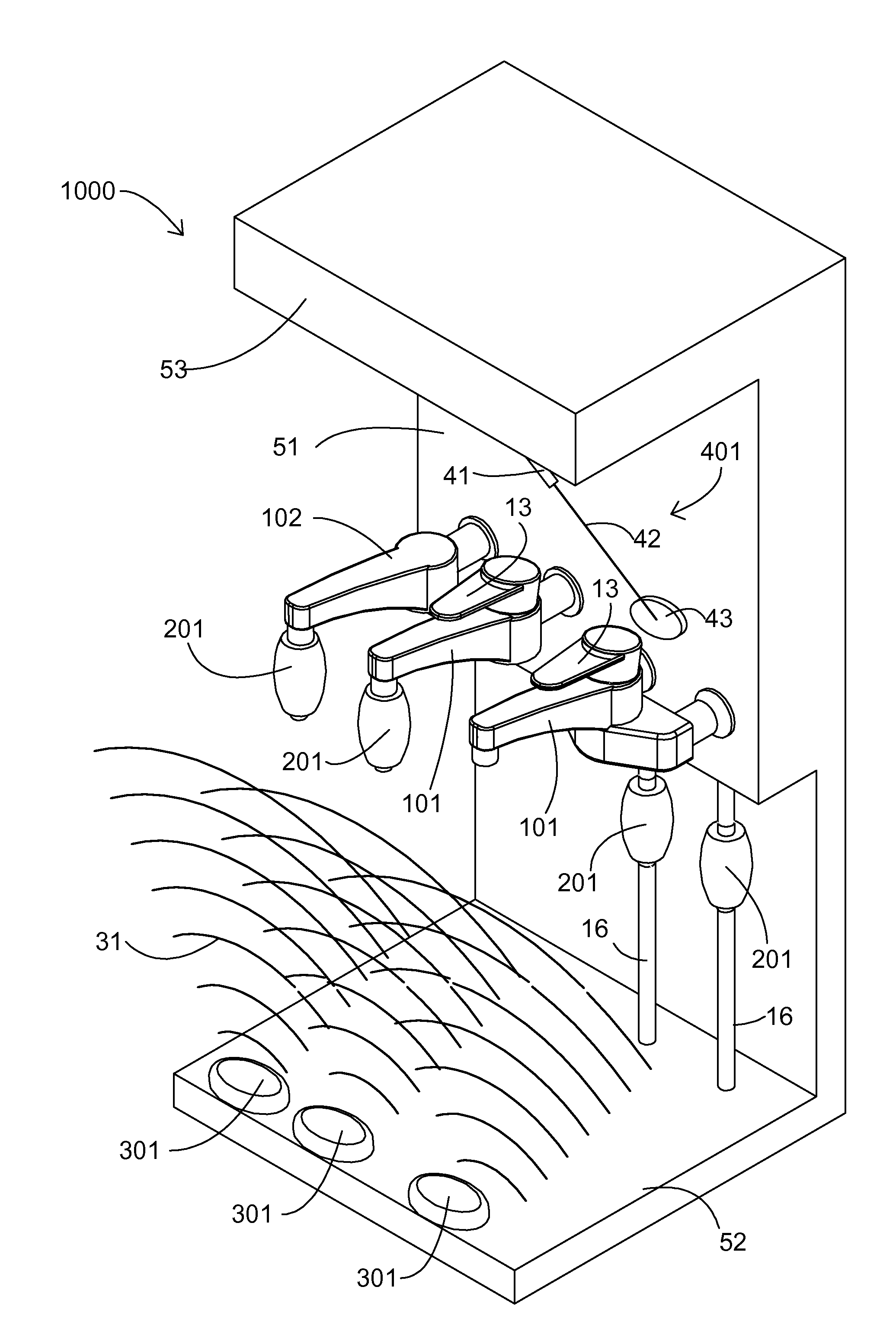
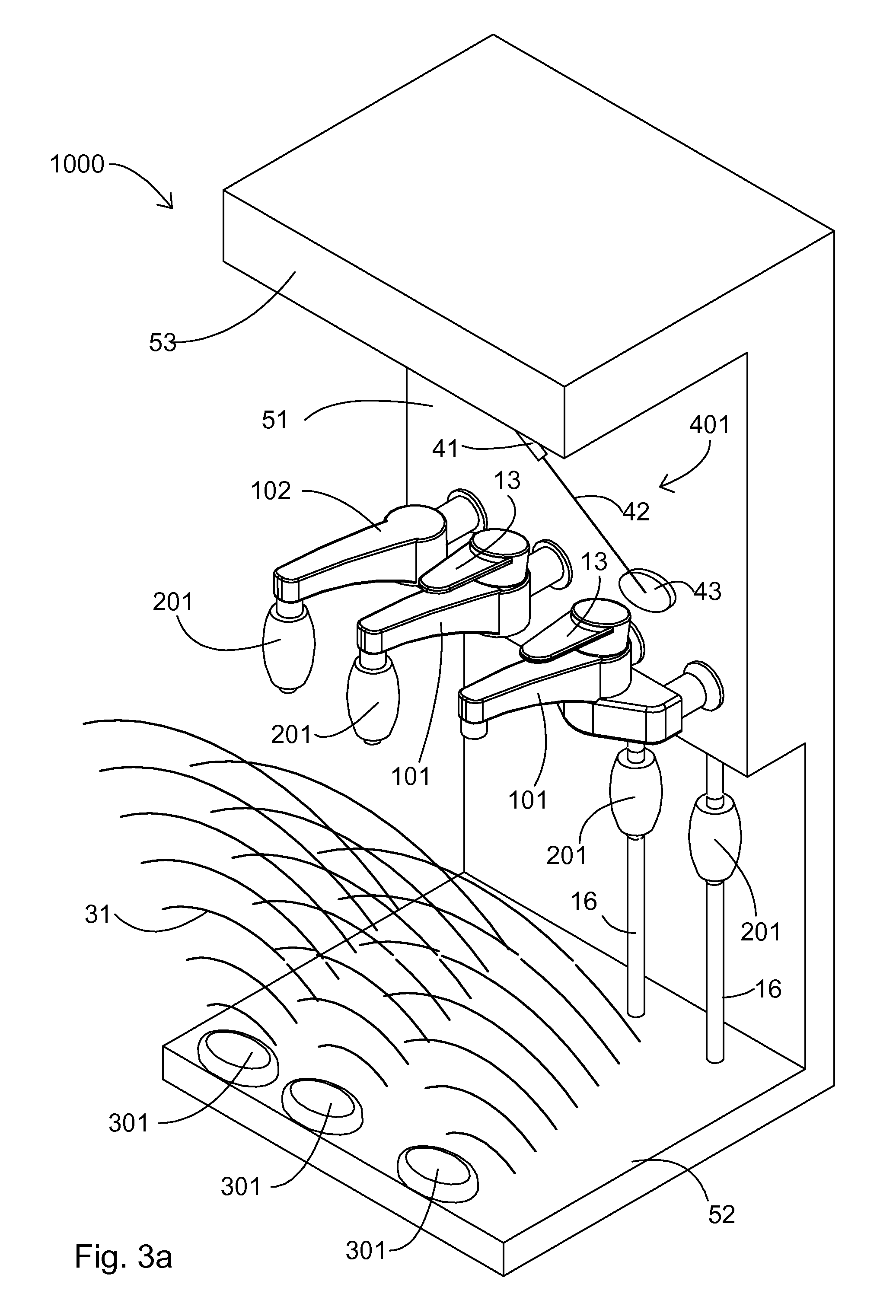
[0069]The present invention is of a system for controlling a fluid flow. The principles and operation of the system for controlling a fluid flow according to the present invention may be better understood with reference to the drawings and the accompanying description.

[0070]Before explaining at least one embodiment of the invention in detail, it is to be understood that the invention is not limited in its application to the details of construction and the arrangement of the components set forth in the following description or illustrated in the drawings.

[0071]Unless otherwise defined, all technical and scientific terms used herein have the same meaning as commonly understood by one of ordinary skill in the art to which this invention belongs. The materials, dimensions, methods, and examples provided herein are illustrative only and are not intended to be limiting.

[0072]The following list is a legend of the numbering of the application illustrations:[0073]11 screw-down mechanism[0074...


PUM


Abstract

A system for controlling a fluid flow includes a remote controlled fluid valve and a pedal unit. The remote controlled fluid valve includes a RCFV PCB configured to receive electromagnetic transmissions, a gear, an arms mechanism, flexible tube, and an engine for set in rotational motion the gear, wherein the rotational motion is transformed to linear motion by the arms mechanism, for pressing on the flexible tube and thus blocking the flexible tube to a fluid flow. The pedal unit includes a tact switch, and a PU PCB, wherein when the tact switch is pressed, the PU PCB is transmitting electromagnetic command signal, wherein the electromagnetic command signal is compatible with the electromagnetic transmissions. An additional option for operation of the remote controlled fluid valves is by means of a ray cut operating system, which also includes a ray transmitter, and a ray receiver and communication transmitter.

Description

REFERENCE TO CROSS-RELATED APPLICATION[0001]This application claims priority from U.S. Provisional Application No. 61 / 241,908, filed on Sep. 13, 2009, herein incorporated by reference in its entirety.FIELD OF THE INVENTION[0002]The present invention relates to faucets, more particularly, to a system for controlling fluid flow.BACKGROUND OF THE INVENTION[0003]A faucet (also known as tap, spigot and others), is a valve controlling release of fluids. FIG. 1 of the prior art illustrates a faucet having a screw-down mechanism 100, having a screw-down mechanism 11 and a faucet interior valve mechanism 12, a part of whose side has been removed to show its content.[0004]Screw-down mechanisms have been in use since the 19th century. They enable prevention of the flow of fluids, as well as regulation of quantities, and are very commonly in use, particularly in water supply systems.[0005]In residential buildings, the use of faucets having a lever 101, (will be shown in following illustrations)...

Claims


Application Information

Patent Timeline
IPC IPC(8): F16K31/08F16K31/02
CPCE03C1/052E03C1/055F16K31/62F16K31/06F16K7/063
Inventor ZELIKOVICH, RAMI A.ARLINSKY, DAVIDPAZ, EYAL
Owner ADMON MISS YONA
Learn More