Differential Cross-Coupled Power Combiner or Divider

Active Publication Date: 2011-03-17
GLOBALFOUNDRIES US INC
View PDF13 Cites 27 Cited by
  • Summary
  • Abstract
  • Description
  • Claims
  • Application Information

AI Technical Summary

Benefits of technology

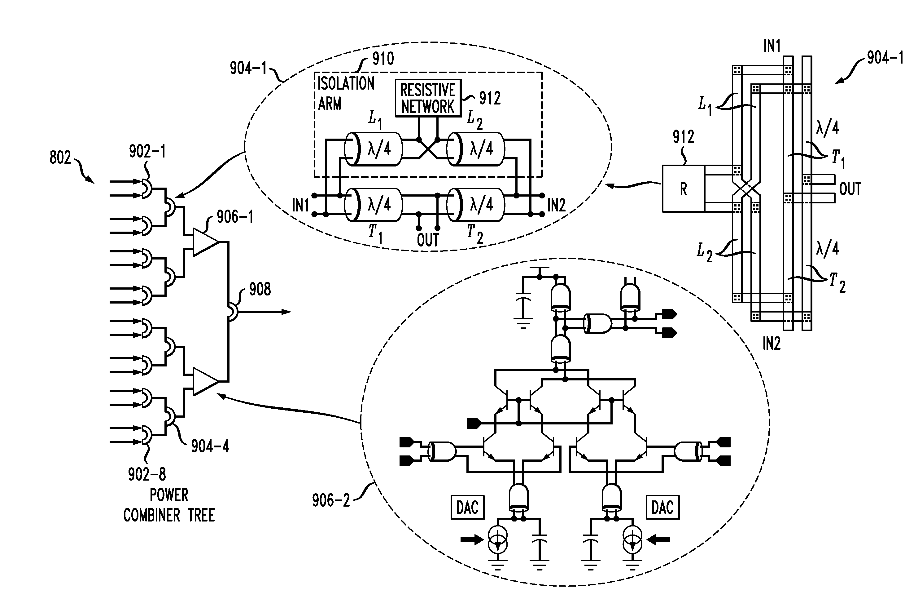
[0010]Illustrative embodiments of the present invention provide a compact N-way differential power combiner or divider in which the inputs or outputs do not need to be physically located close to each other. By cross coupling the differential lines used in an isolation

Problems solved by technology

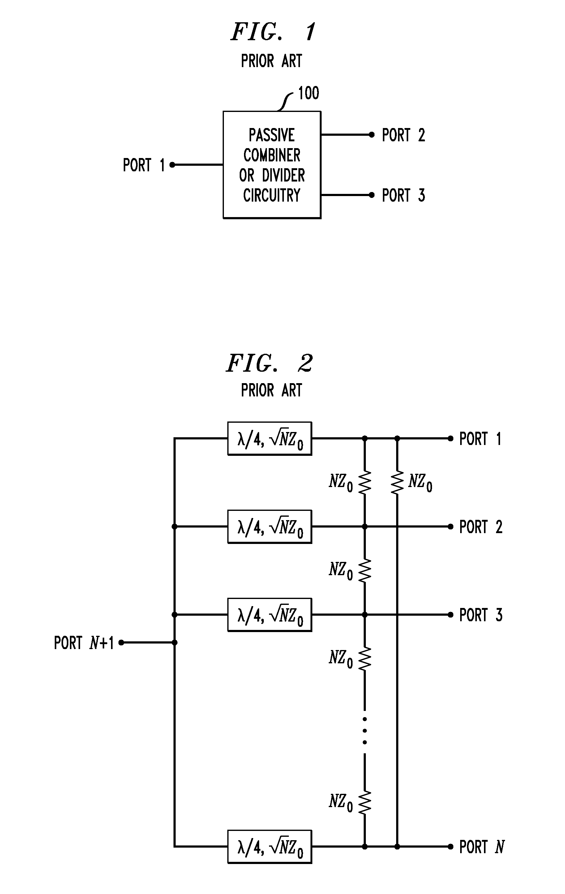
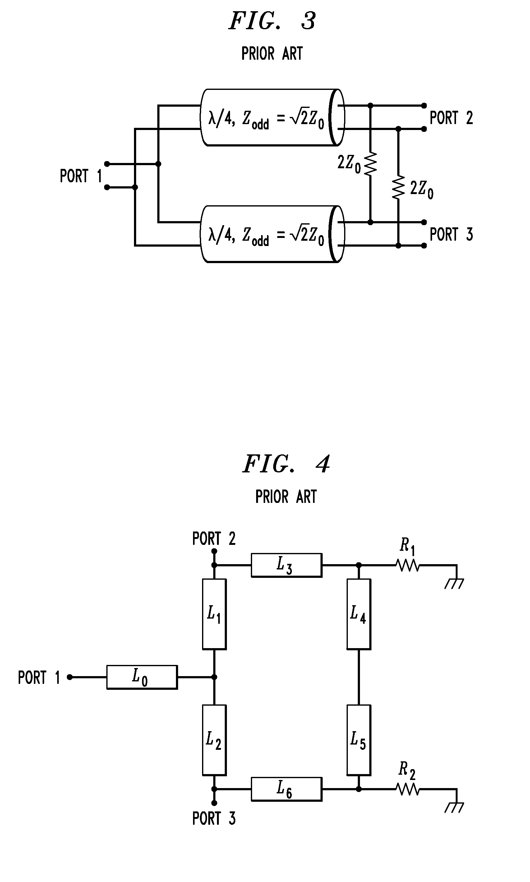
While a Wilkinson combiner is well-suited for certain applications, a major challenge is the fact that the inputs have to be physically close to each other in order to connect the isolation resistor network to the inputs.
Using a Wilkinson combiner in such applications will often require unduly long lines to connect the isolation

Method used


Image

  • Differential Cross-Coupled Power Combiner or Divider
  • Differential Cross-Coupled Power Combiner or Divider
  • Differential Cross-Coupled Power Combiner or Divider

Examples


Example

[0028]The present invention will be illustrated herein in conjunction with power combining or dividing circuitry and associated systems that incorporate that circuitry, such as phased array receivers and transmitters. It should be understood, however, that the invention is not limited to use with the particular types of power combining or dividing circuitry and associated systems that are expressly disclosed. The invention can be implemented using a wide variety of other types of power combining or dividing circuitry, and in numerous other system applications. For example, although certain embodiments are described herein as being implemented in the form of a phased array transmitter or receiver, the disclosed power combining or dividing circuitry can be utilized in alternative applications such as chip to chip signal distribution.

[0029]An illustrative embodiment of the invention is shown in FIG. 5. The device shown may be utilized as an N-way differential power combiner or as an N-...


PUM


Abstract

A differential cross-coupled power combiner in one aspect comprises a plurality of inputs, an output, a plurality of differential transmission lines each coupled between a corresponding one of the inputs and the output, and at least one set of additional differential transmission lines arranged in series between any two of the inputs. First and second ones of the additional differential transmission lines in the set are coupled to one another using a cross-coupling arrangement. Other aspects of the invention provide a differential cross-coupled power divider, communication system receivers and transmitters incorporating respective power combiners and dividers, and integrated circuit implementations of power combiners and dividers.

Description

RELATED APPLICATION[0001]The present application claims the priority of U.S. provisional patent application Ser. No. 61 / 241,950, filed Sep. 13, 2009 and entitled “Differential Power Combiner with Common Mode Rejection and Frequency Filtering,” the disclosure of which is incorporated by reference herein.FIELD OF THE INVENTION[0002]The present invention relates generally to power combining or dividing circuitry, and more particularly to power combining or dividing of electrical signals.BACKGROUND OF THE INVENTION[0003]Power combiners or dividers are used in a wide variety of signal combination or distribution applications. By way of example, one such application is in radio frequency (RF) phased array receivers and transmitters. Generally, a power combiner combines multiple input signals into a single output signal, and a power divider divides a single input signal into multiple output signals. Power combiners or dividers that do not require any power supply are referred to as passive...

Claims


Application Information

Patent Timeline
IPC IPC(8): H01P5/12
CPCH01P5/16H03F3/602
Inventor FLOYD, BRIAN ALLANNATARAJAN, ARUN SRIDHARREYNOLDS, SCOTT KEVINSOYUER, MEHMETVALDES GARCIA, ALBERTO
Owner GLOBALFOUNDRIES US INC
Why Eureka
Try Eureka