Integrity Test Method for Porous Filters

a technology of integrated test and porous filter, which is applied in the analysis of porous materials, instruments, suspensions, etc., can solve the problems of large bulk gas flow rate, compromise device performance, and device defects,

Active Publication Date: 2011-03-24
WL GORE & ASSOC INC
View PDF8 Cites 29 Cited by
  • Summary
  • Abstract
  • Description
  • Claims
  • Application Information

AI Technical Summary

Problems solved by technology

With membrane filtration devices, integrity testing assures that the membrane is free of defects of a certain size, the presence of which would compromise device performance by allowing the end product to be contaminated.
A device with defects however, will exhibit relatively large, bulk gas flow rates attributable to gas flowing through the defects in the porous filter.
For large multi-round housings with large porous filter areas, the diffusive flow through the filter material is often so high, however, that it cannot be distinguished from bulk flow attributable to small defects.
Similarly, devices using extremely thin membranes such as those described in U.S. Pat. No. 7,306,729, have inherently high diffusive flow through the membrane which may make it difficult to recognize flow due to a defect.
Therefore, the utility of the gas-liquid diffusion test for large filtration devices is limited.

Method used


Image

  • Integrity Test Method for Porous Filters
  • Integrity Test Method for Porous Filters
  • Integrity Test Method for Porous Filters

Examples


example 1

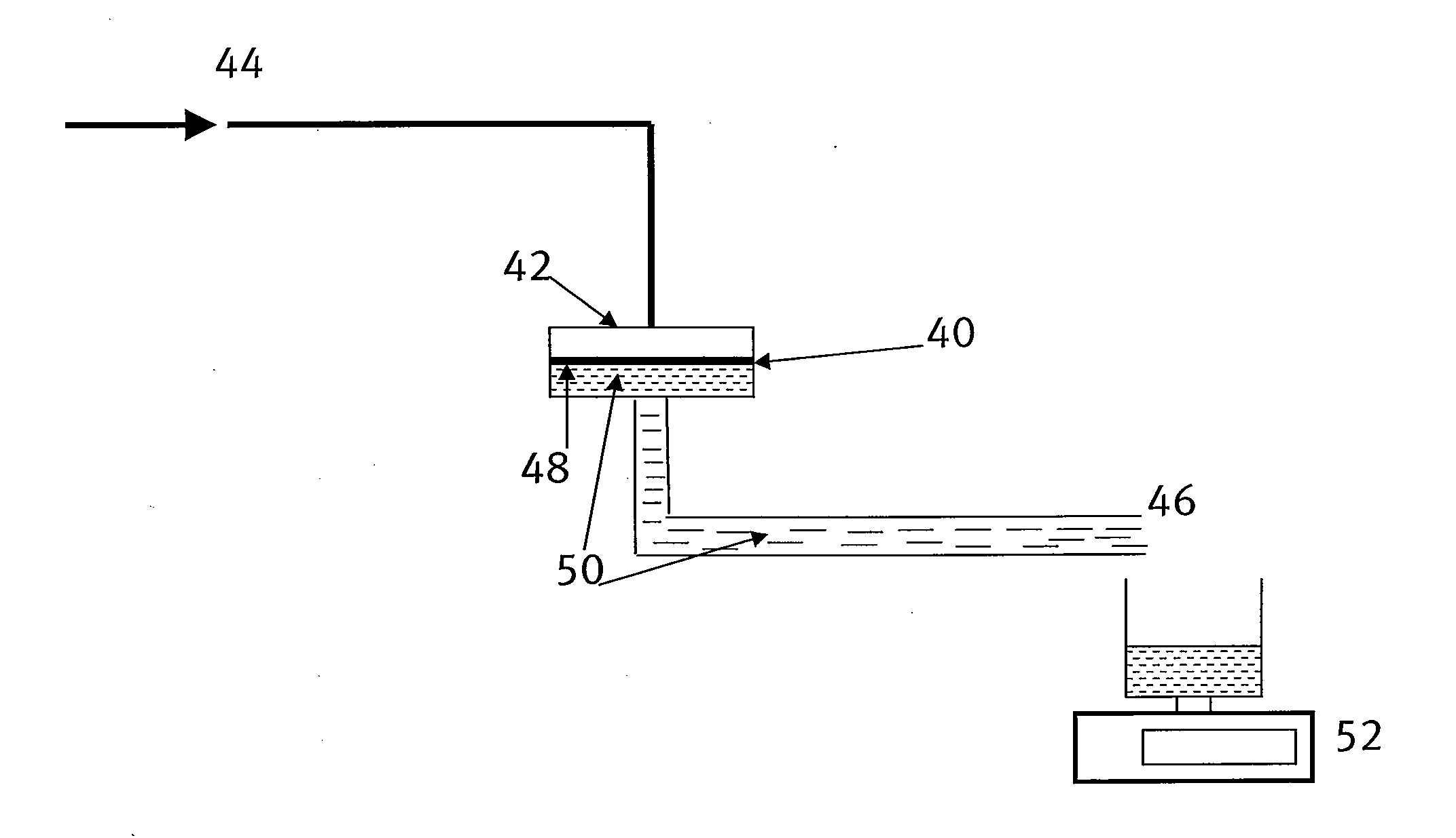
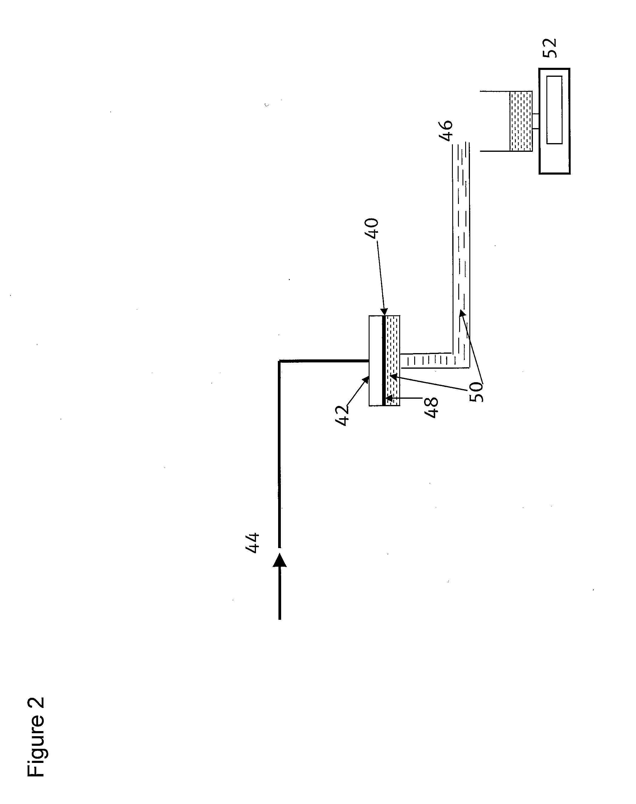
[0034]The integrity test method of the present invention was carried out on an expanded PTFE (ePTFE) membrane made according to the teachings of U.S. Pat. No. 7,306,729. The membrane had an air flow of 2.6 Gurley secs and mass per area of 1.6 grams / m2. A flat disk of this membrane, 47 mm in diameter was installed in a test fixture. The sample was wetted with IPA by circulating through the sample for about 5 minutes. As described in FIGS. 2 and 3, the portion of the test fixture between the downstream side of the sample and the outlet was filled with the wetting liquid IPA to create a liquid conduit.

[0035]After wetting the sample and filling downstream portions of the test apparatus with IPA, the sample was pressurized using air. Air pressure was slowly increased at a rate of 10 psi / min. The mass of IPA displaced was collected in a container and measured every second using a balance (Model CPA324S, Sartorius Corporation). The IPA flow rate was converted to volumetric gas flow rate by...

example 2

[0037]The integrity test method of the present invention was carried out on a hydrophilic PVDF filter (rated pore size of 0.1 um, Durapore®, Millipore Corporation). The sample was wetted with IPA by circulating through the sample for about 5 minutes. As described above, the portion of the test fixture between the downstream side of the sample and the outlet was filled with IPA to create a liquid conduit. The sample was pressurized using air; Air pressure was slowly increased at a rate of 10 psi / min. The mass of IPA displaced was collected in a container and measured every 10 seconds using a balance. The mass flow rate was converted to volumetric liquid flow rate by dividing the mass flow rate by the density of IPA. FIG. 5 depicts the volumetric liquid flow rate (in cc / min) as a function of pressure. As shown in FIG. 5, the measured flow rate through the membrane sample in the region D-E was very low, on average less than 0.015 cc / min. In the region E-F, the bubble point of the sampl...

example 3

[0038]The integrity test method of the present invention was carried out on a PVDF filter cartridge. A commercial cartridge (Durapore®, rated pore size 0.22 um, Millipore Corporation) was installed in a test fixture (Part Number CSF 786-226, Shelco Filters). The cartridge sample was wetted with IPA by circulating through the sample for 60 minutes. As described above, the portion of the test fixture between the downstream side of the sample and the outlet was filled with IPA to create a liquid conduit. The sample was pressurized using air; the air pressure was held constant at 10 psi. The mass of IPA displaced was collected in a container and measured every 10 seconds using a balance. The mass flow rate was converted to volumetric liquid flow rate by dividing the mass flow rate by the density of IPA. FIG. 6 depicts the volumetric liquid flow rate (in cc / min) decay as a function of time. As shown in FIG. 6, liquid flow rate as low as 0.03 cc / min can be measured using this technique.


PUM

PropertyMeasurementUnit
diffusive flow rateaaaaaaaaaa
differential pressureaaaaaaaaaa
thicknessaaaaaaaaaa

Abstract

An improved method of testing the integrity of a porous filter is provided. The test method is an improvement over a gas-liquid diffusion test wherein the improvement comprises providing a conduit downstream of the filter and filling the conduit with a liquid, the conduit having a length to cross sectional area ratio selected to substantially resist diffusive flow of the gas through the liquid downstream of the filter material.

Description

RELATED APPLICATION[0001]The present application is related to provisional application Ser. No. 61 / 245,493 filed Sep. 24, 2009.BACKGROUND OF THE INVENTION[0002]Porous materials such as membranes are used as filtration devices to eliminate undesirable contaminants from useful end products. Pharmaceutical, food processing and biotechnology industries require that the filtration devices comply with certain performance criteria. Integrity testing provides a means for ensuring that the device meets the desired performance criteria. With membrane filtration devices, integrity testing assures that the membrane is free of defects of a certain size, the presence of which would compromise device performance by allowing the end product to be contaminated.[0003]One known integrity test method is the gas-liquid diffusion test, this test measures the flow of a gas through a liquid-wetted porous filter when the filtration device is pressurized on one side with the gas at a set pressure below the b...

Claims


Application Information

Patent Timeline
Patent Type & Authority Applications(United States)
IPC IPC(8): G01N15/08
CPCG01N2015/084B01D65/102
Inventor GRANT, DONALD C.BEUSCHER, UWEROSS, SCOTT
Owner WL GORE & ASSOC INC
Why Eureka
Try Eureka