

Processing Cap Assembly for Isolating Contents of a Container
a processing cap and container technology, applied in the field of cap assembly for venting and isolating containers, can solve the problems of contamination, high cost of freeze-drying equipment, cross-contamination of different batches of products at the same time, etc., and achieve the effects of preventing contamination (of products, workers, equipment), reducing re-validation requirements, and reducing the possibility of contamination
- Summary
- Abstract
- Description
- Claims
- Application Information
AI Technical Summary
Benefits of technology
Problems solved by technology
Method used
Image

Examples
example 1
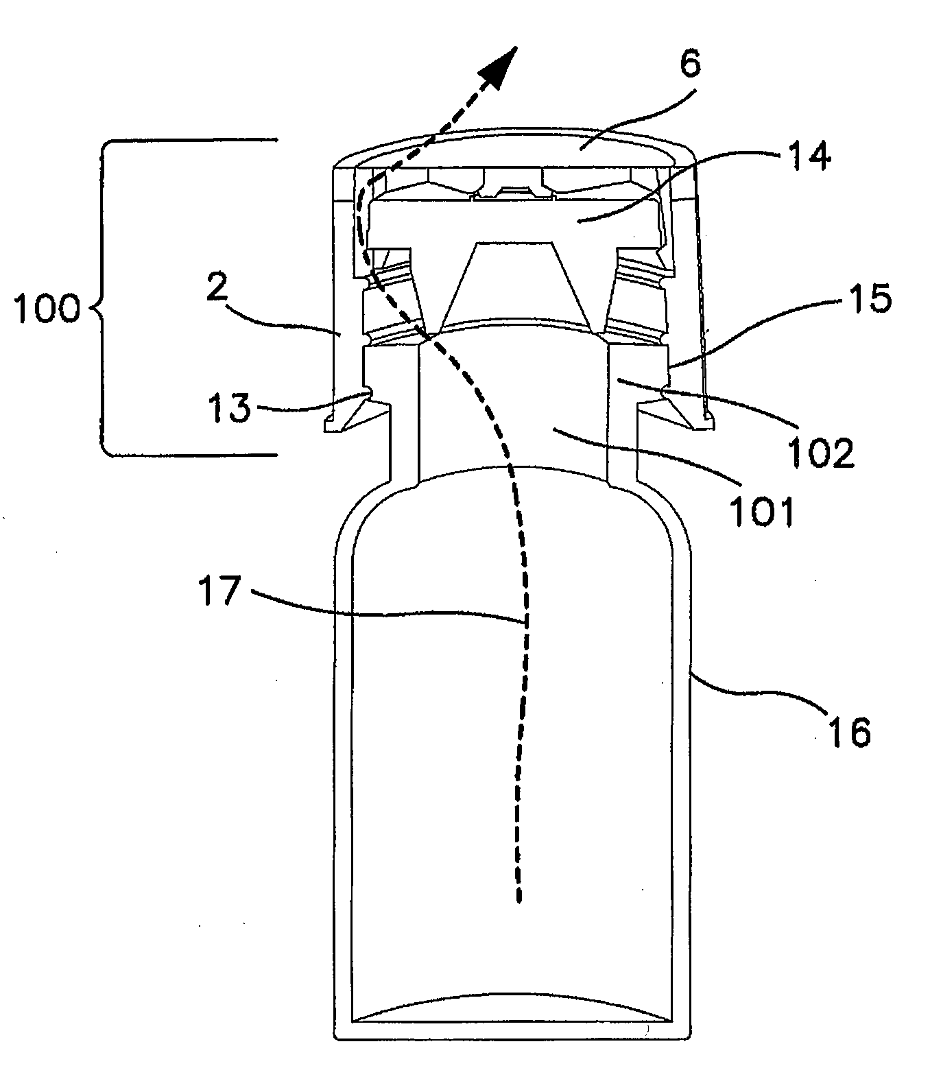
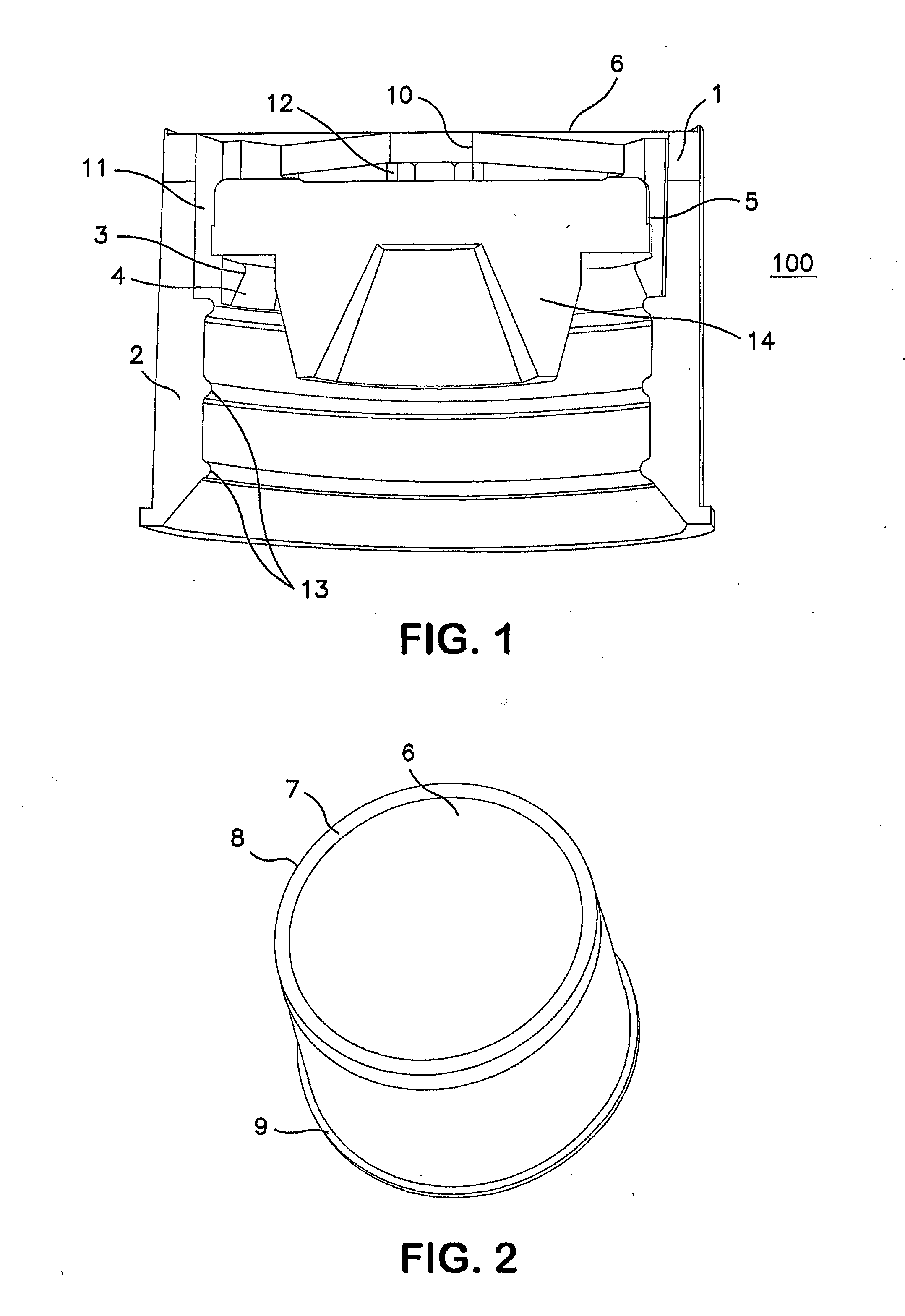
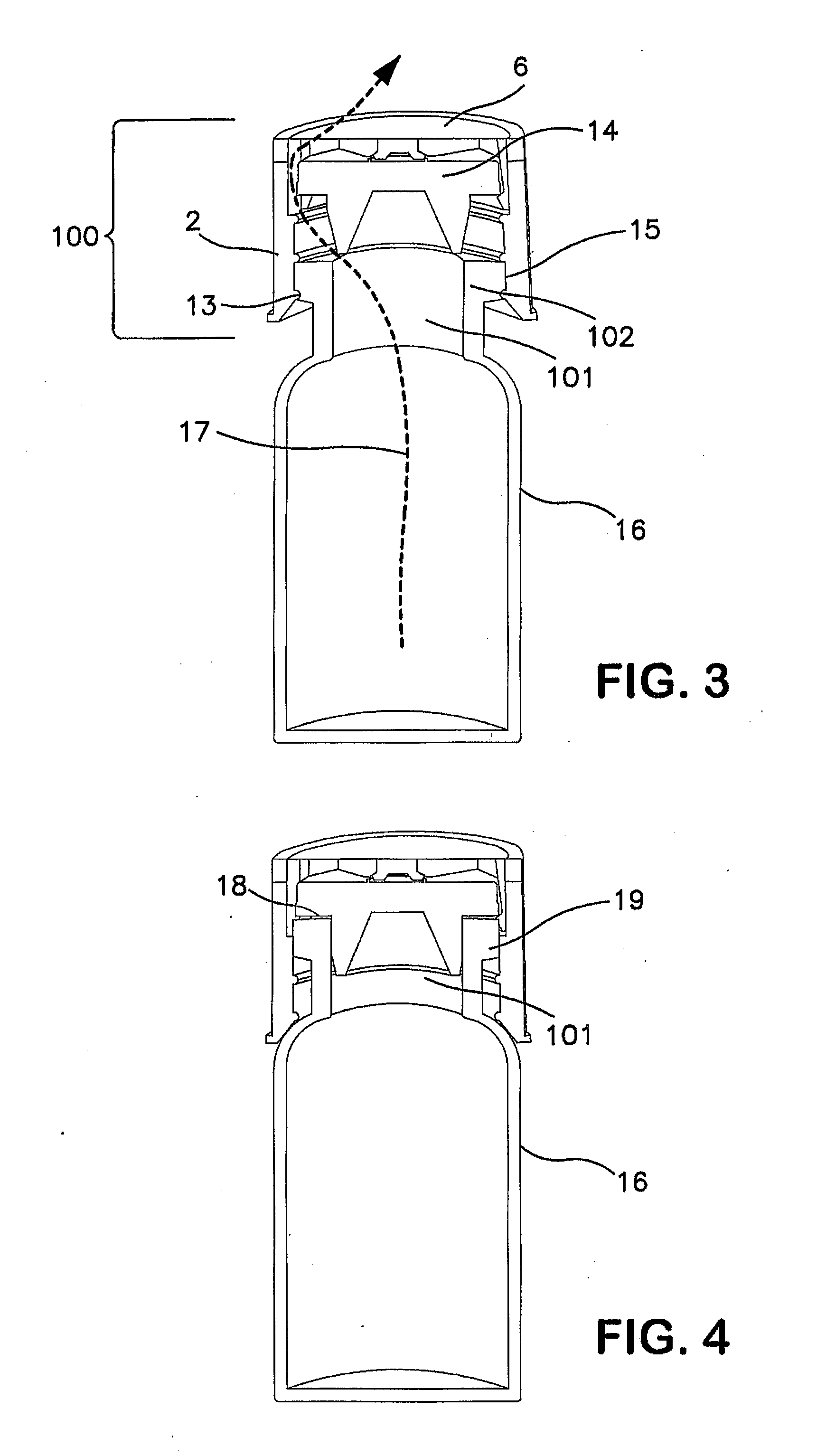
[0095]A two-part, or “two-shot” cap assembly of the present invention with a geometry substantially as shown in FIGS. 1-5 was formed in the following manner.
[0096]A mold was created to provide a cap assembly with the geometry of the part described below. The mold comprised two halves, an “A” side and a movable “B” side, and the rigid housing component was first molded from PRO-FAX 6323® polypropylene resin (Montell Polyolefins, Wilmington, Del.). The polypropylene housing had the general shape of a ring with an outside diameter of about 0.92 inches (23.4 mm), an inside diameter of about 0.74 inches (18.8 mm), and a height of about 0.29 inches (7.37 mm). Vent slots were located in the inner wall at 45°, 135°, 225°, and 315° to a depth of about 0.036 inches (0.914 mm). Crossbars measuring 0.100 inches (2.54 mm) wide and 0.080 inches (2.03 mm) thick were oriented at the top of the part at 0°, 90°, 180°, and 270° for supporting the venting media and providing a stop against which a stop...
example 2
[0103]A two-part, or “two-shot,” cap assembly of the present invention was formed as described in Example 1.
[0104]The venting media to be attached to the cap assembly was a laminate (labeled “B”) of an ePTFE membrane having a reference pore size of 1.0 micron (W. L. Gore and Associates, Inc., Elkton, Md.) bonded to a non-woven polyester material (Part Number B3005, HDK Industries Inc., Rogersville, Tenn.). Material B had the following measured laminate properties: Gurley 0.8 seconds, water entry pressure (WEP) of 39.4 psi, a thickness of 9 mils, and a bubble point of 11.2 psi. The laminate was cut using a hand punch measuring 0.94 inches (23.8 mm) in diameter. It was then adhered to the cap using a ring (0.94 inches (23.8 mm) O.D., 0.81 inches (20.6 mm) I.D.) of double sided silicone adhesive (Specialty Tapes, part number D650).
[0105]Serum stoppers (West Pharmaceuticals, part number 19500080) were then inserted into the caps so that they were held tight by dimple 3. Vials (Part No. ...
example 3
[0107]A single-part, machined cap assembly of the present invention with a geometry substantially as shown in FIG. 6 was formed in the following manner.
[0108]A polypropylene rod measuring about 1 inch (25.4 mm) in diameter was cut to a length of about 0.7 inches (17.8 mm), and the rod was machined to hollow out the interior, creating a cap with an inside diameter slightly smaller than 0.78 inches (19.8 mm), which is slightly smaller than the outside diameter of a rubber stopper (Part No. 19500080, West Pharmaceutical Services, Inc., Lionville, Pa.), which allowed the cap to grip and hold the outside surface of the stopper. Vent slots were cut at 0°, 90°, 180°, and 270° into the cap to allow for venting around the stopper, and a through-hole measuring 0.60 inches (15.24 mm) was machined into the center of the cap to provide more venting area above the stopper. The venting media was attached over this through-hole. A chamfer was then machined into the bottom of the cap to accommodate ...
PUM
 Abstract
Description
Claims
Application Information