Mold Tool and Treatment Method for Mold Tool Surface
a mold tool and treatment method technology, applied in the field of mold tool and treatment method for mold tool surface, can solve the problem of dimension error of several tens of m that is not allowable, and achieve the effect of reducing the release resistan
- Summary
- Abstract
- Description
- Claims
- Application Information
AI Technical Summary
Benefits of technology
Problems solved by technology
Method used
Image

Examples
experiment 1
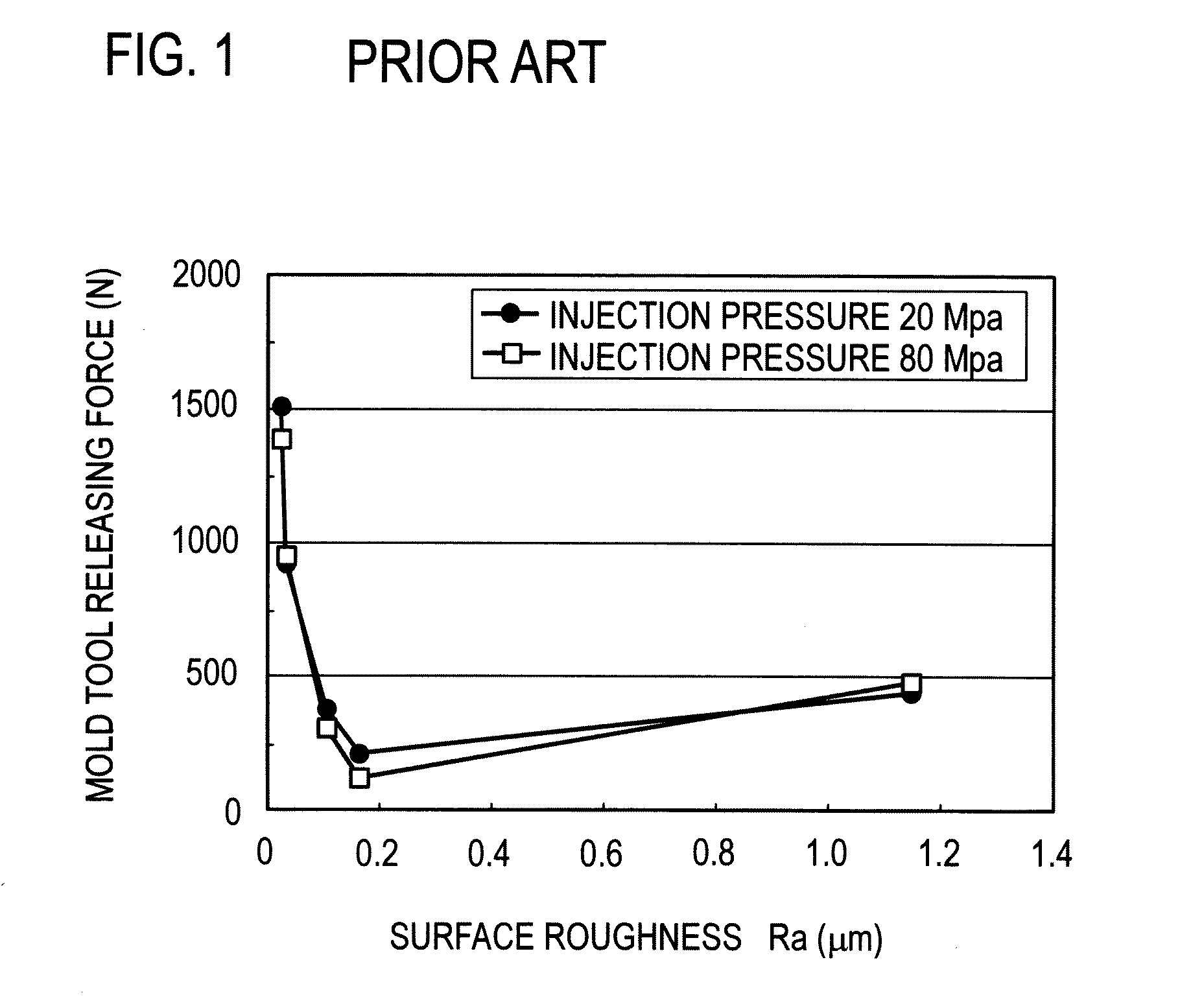
[0036]The relationship between the geometry of a surface of an injection mold tool that comes into contact with resin and the releasability of resin was examined.
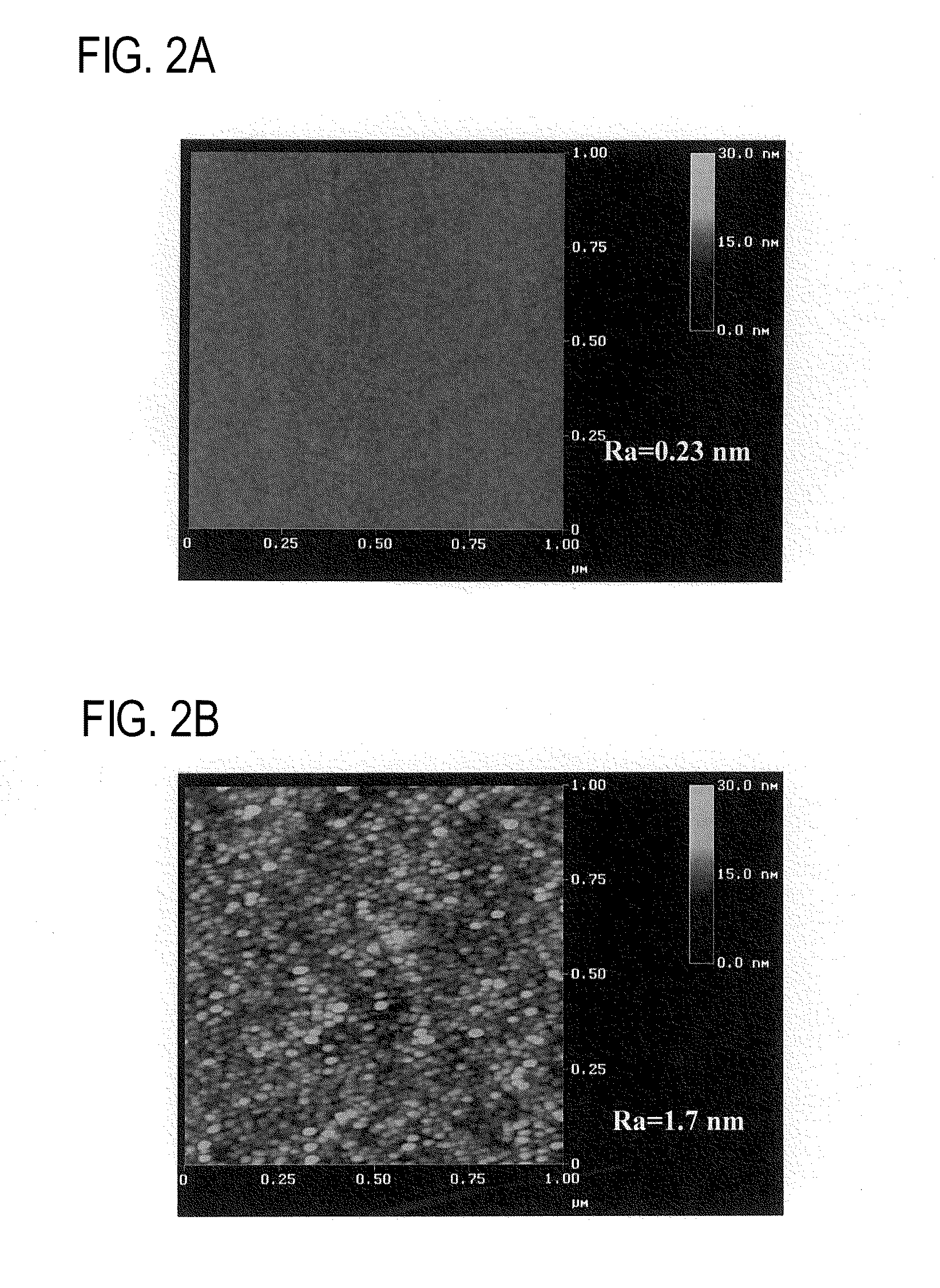
[0037]Using the tool steel SKD61 as the material of the mold tool and a liquid crystal polymer as the resin material, a thin rectangular parallelepiped resin part having a length of 35 mm, a width of 3 mm and a height of 0.2 mm was molded. Three types of mold tools (mold tools 1 to 3) having different surface geometries were prepared. The surface of the mold tools 1 to 3 was treated as described below.
[0038]Mold tool 1: Ground with #400 grindstone
[0039]Mold tool 2: Ground with #600 grindstone
[0040]Mold tool 3: Ground with #600 grindstone and irradiated with gas cluster ion beam
[0041]The irradiation with gas cluster ion beam was carried out under conditions that an Ar cluster ion beam was used, the acceleration energy was 20 keV, and the irradiation fluence was 5.0×10¹⁷ ions / cm2.
[0042]The set resin part was released from the...
experiment 2
[0045]The relationship between the surface geometry of injection mold tools of the same type as those in the experiment 1 (except that the material was SKD11) and the releasability of the resin contact surface thereof was examined for various gas cluster ion beam irradiation conditions.
[0046]The gas cluster ion beam irradiation conditions were that an Ar cluster ion beam was used, and the acceleration energy Va, the irradiation angle θ and the irradiation fluence N were changed as shown in the table 2 shown in FIG. 7. The table 3 shown in FIG. 8 shows results of measurement of the density, the height and the diameter of fine granular projection structures formed by irradiation on the resin contact surface of mold tools 4 to 7 shown in the table 2 and the average roughness Ra for an area 1 μm square of the mold tools 4 to 7. No fine granular projection structures were observed on the mold tool surface that was not irradiated. In addition, the rate of successful releasing was examined...
experiment 3
[0047]Mold tools of the same type as those in the experiment 1 were made of SKD11 (tool steel) or V20 (a carbide material made of tungsten carbide and cobalt (Co) as a binder), and the relationship between the irradiation fluence of a gas cluster ion beam and the changes of the surface geometry was examined.
[0048]The gas cluster ion beam irradiation conditions were that the mold tool surface was perpendicularly irradiated with an Ar cluster ion beam with an acceleration energy of 20 keV. FIG. 9 is a graph showing a relationship between the irradiation fluence and the average roughness Ra evaluated for an area 1 μm square. The small graphs in the graph are enlarged graphs showing Ra for the mold tools made of SKD11 and V20 over a narrower range of irradiation fluence. Fine granular projection structures similar to those shown in FIG. 5D were observed when the irradiation fluence was equal to or higher than 2×10¹⁶ ions / cm2 for the mold tool made of SKD11 and when the irradiation fluen...
PUM
| Property | Measurement | Unit |
|---|---|---|
| roughness Ra | aaaaa | aaaaa |
| heights | aaaaa | aaaaa |
| heights | aaaaa | aaaaa |
Abstract
Description
Claims
Application Information
PatSnap Eureka turns technology decisions into work you can execute. Powered by our Innovation Knowledge Graph, it runs expert workflows across engineering, life sciences, materials and intellectual property. Get your review-ready output in minutes.


