Sensor system and method for manufacturing a sensor system

a sensor system and sensor technology, applied in the direction of fluid pressure measurement, fluid pressure measurement by electric/magnetic elements, instruments, etc., can solve the problems of diaphragm area deformation, achieve cost-effectiveness, improve measurement accuracy, and reduce the effect of second pressure variation

Inactive Publication Date: 2011-03-31
ROBERT BOSCH GMBH
View PDF3 Cites 2 Cited by
  • Summary
  • Abstract
  • Description
  • Claims
  • Application Information

AI Technical Summary

Benefits of technology

[0002]The sensor system according to the present invention and the method according to the present invention for manufacturing a sensor system have the advantage over the related art that mechanical decoupling of the diaphragm area from a second pressure on the second side of the substrate is achieved. This is accomplished in that the decoupling element is introduced into the material of the diaphragm area. A pressure variation of the second pressure thus does not result in a deflection movement of the diaphragm area perpendicularly to the main extension plane, but rather is instead absorbed by the decoupling element. A deflection movement of the diaphragm area perpendicularly to the main extension plane is advantageously exclusively caused by a variation of a first pressure in the trench, so that a detected deflection movement is uniquely to be assigned to this first pressure. The sensor system is thus usable as an absolute pressure sensor. The measuring precision of the sensor system is further increased overall and the impairment of the measuring precision by variations of the second pressure is reduced. Advantageously, a further absolute pressure sensor or a further reference volume is thus not required, so that costly capping of the sensor system or the second side of the substrate may be dispensed with. The integration of the decoupling element in the diaphragm area further allows implementing a comparatively compact installation, and cost-effective manufacturing of the sensor system. The substrate preferably includes a semiconductor substrate and particularly preferably a silicon substrate.
[0003]According to a preferred specific embodiment, it is provided that the decoupling element includes a cavern, the cavern preferably being smaller along the main extension plane than the diaphragm area and / or the diaphragm area having a further diaphragm area in the area of the cavern. A comparatively cost-effective implementation of a decoupling element is thus advantageously implemented. A pressure variation of the second pressure is absorbed by a decoupling movement of the further diaphragm area perpendicularly to the main extension plane, so that the action of a force on the diaphragm area perpendicularly to the main extension plane is prevented. A vacuum, which damps the decoupling movement in the desired manner, is preferably hermetically enclosed inside the cavern. The further diaphragm area has a lower material thickness in comparison to the diaphragm area, in particular perpendicularly to the main extension plane. The further diaphragm area preferably includes an APSM diaphragm (advanced porous silicon membrane). The diaphragm area and / or the further diaphragm area include a round or polygonal, preferably square cross-section parallel to the main extension plane in particular.
[0006]According to a preferred specific embodiment, it is provided that the trench is provided extending essentially perpendicularly to the main extension plane from the first side up to the first diaphragm area. The sensor system thus advantageously has a comparatively high media resistance, because the first pressure to be measured is supplied to the diaphragm area through the trench from the first side of the substrate, in particular the rear side of the substrate, so that a pressure measurement of aggressive media is advantageously achievable.
[0008]A further object of the present invention is a method for manufacturing a sensor system, the substrate being provided in a first manufacturing step, the decoupling element being manufactured in a second manufacturing step, and the trench being manufactured in a third manufacturing step. The sensor system is thus producible comparatively cost-effectively, standard micromechanical manufacturing methods (preferably in surface micromechanics), for example, in 200 mm technology, being usable in particular.
[0009]According to a preferred specific embodiment, it is provided that in a fourth manufacturing step, the detection elements and / or the analysis circuit are placed in the area of the second side. The detection elements and / or the analysis circuit may advantageously be manufactured cost-effectively and using a comparatively compact installation space in standard semiconductor manufacturing methods.

Problems solved by technology

This sensor system has the disadvantage that both a variation of the first pressure and also a variation of the second pressure directly result in a deformation of the diaphragm area.

Method used


Image

  • Sensor system and method for manufacturing a sensor system
  • Sensor system and method for manufacturing a sensor system
  • Sensor system and method for manufacturing a sensor system

Examples


Embodiment Construction

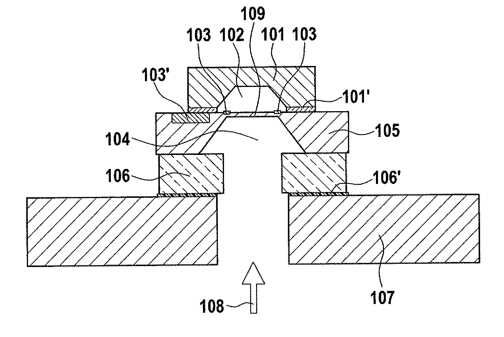
[0018]A schematic side view of a sensor system according to the related art having a sensor substrate 105, a sensor cavern 104, and a sensor diaphragm 109, is shown in FIG. 1, sensor substrate 105 being connected to a glass base 106, glass base 106 being glued on a circuit board 107 using an adhesive 106′. Circuit board 107 and glass base 106 each have an opening, so that a pressure 108 reaches sensor cavern 104 from a bottom side of circuit board 107 and sensor diaphragm 109 is deformed as a function of pressure 108 and as a function of a reference pressure 102. This deformation is measured using piezoresistors 103 on the top side of sensor diaphragm 109 and analyzed using an analysis circuit 103′. The top side of sensor diaphragm 109 has a hermetically sealed cap 101, which functions to set known reference pressure 102. The absolute value of pressure 108 may be determined using the relative measurement between reference pressure 102 and pressure 108 by setting known reference pres...


PUM

PropertyMeasurementUnit
areaaaaaaaaaaa
thicknessaaaaaaaaaa
pressureaaaaaaaaaa

Abstract

A sensor system, in particular a pressure sensor system, having a substrate having a main extension plane, the substrate having at least one trench on a first side, and the trench being provided to produce a diaphragm area on a second side of the substrate diametrically opposite to the first side perpendicularly to the main extension plane, and a decoupling element further being integrated in the material of the diaphragm area.

Description

BACKGROUND INFORMATION[0001]Sensor systems are generally known. For example, a sensor and a method for manufacturing a sensor are known from German Patent No. DE 102 26 034, the sensor including a semiconductor material, which has a first thickness inside a diaphragm area and a second thickness outside the diaphragm area, the second thickness being greater than the first thickness. The semiconductor material has an open trench, which is defined by the lesser first thickness, on its rear side. The diaphragm area, which is implemented on a front side of the semiconductor material, is deformable perpendicularly to the semiconductor material as a function of a pressure differential between a first pressure on the front side and a second pressure, which is to be measured, in the trench, means for measuring the deformation of the diaphragm area being situated in the junction area between the first and the second thicknesses. This sensor system has the disadvantage that both a variation of...

Claims


Application Information

Patent Timeline
Patent Type & Authority Applications(United States)
IPC IPC(8): G01L9/06H05K3/00
CPCG01L19/147Y10T29/49124G01L19/148
Inventor AHLES, MARCUSBENZEL, HUBERT
Owner ROBERT BOSCH GMBH
Why Eureka
Try Eureka