Solar cell module

a solar cell and module technology, applied in the field of thin film solar cell modules, can solve the problems of unnecessary operation of earth leakage breaker, and achieve the effects of minimizing adverse effects, reducing potential differences, and increasing withstand voltag

Inactive Publication Date: 2011-03-31
FUJIFILM CORP
View PDF10 Cites 7 Cited by
  • Summary
  • Abstract
  • Description
  • Claims
  • Application Information

AI Technical Summary

Benefits of technology

[0024]The present invention permits minimizing the adverse effects produced by the stray capacitance generated between the electric power generation layer of the solar cells and the metal substrate, minimizing the potential difference between them, eliminating the need to increase the withstand voltage of the insulation layer between the electric power generation layer and the metal substrate, and increasing the output voltage per module. As a result, the present invention enables a high-voltage solar cell module to be obtained.
[0025]Further, the present invention permits construction of a solar photovoltaic power g

Problems solved by technology

Closing the system interconnection switch can therefore trigger flow of a feeble leak current due to the stray capa

Method used


Image

  • Solar cell module
  • Solar cell module
  • Solar cell module

Examples


second embodiment

[0030]FIG. 5 is a cross section schematically illustrating the solar cell module illustrated in FIG. 1.

[0031]FIG. 6 is a view schematically illustrating an example of configuration of a solar photovoltaic system using solar cell modules of the invention.

[0032]FIG. 7 is a schematic cross section illustrating a conventional solar cell module.

DETAILED DESCRIPTION OF THE INVENTION

[0033]The solar cell modules according to the invention will be described in detail based upon preferred embodiments referring to the attached drawings.

first embodiment

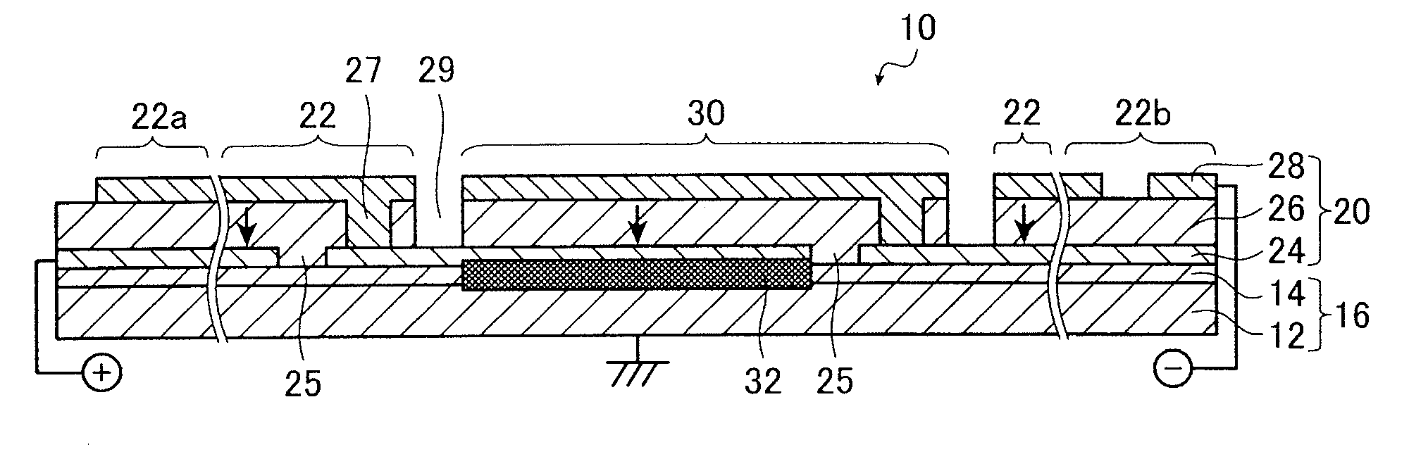
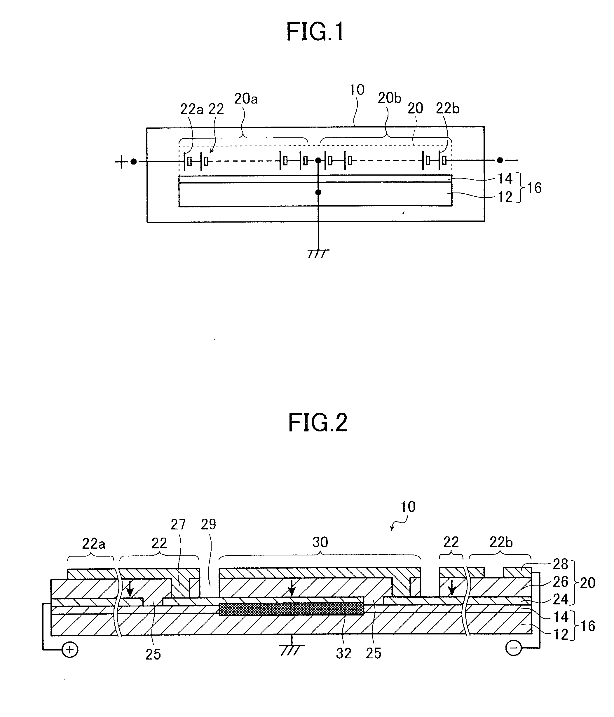
[0034]FIG. 1 is a view of a circuit configuration schematically illustrating an example of solar cell module according to the invention. FIG. 2 is a cross section schematically illustrating the solar cell module of FIG. 1.

[0035]As illustrated in FIG. 1, a solar cell module 10 according to the invention comprises, for example, a support substrate 16 including a grounded, substantially rectangular metal substrate 12 and an electric insulation layer 14 formed on the metal substrate 12 and a power generation layer 20 including series-connected solar cells 22 formed on the insulation layer 14.

[0036]In the solar cell module 10 of the invention, the positive polarity (plus) side of a solar cell 22a located at one end of the solar cells 22 in the power generation layer 20, used as a positive terminal, is connected to the positive terminal of a connection box, not shown, through a ribbon cable, not shown, while the negative polarity (minus) side of the solar cell 22b located at the other end...


PUM


Abstract

A solar cell module includes a metal substrate, an insulation layer, series-connected solar cells, two output terminals, and a ground terminal. Each solar cell includes an underside electrode layer, a photoelectric conversion layer and a transparent electrode layer. The solar cell module further includes an electrical conductive layer for electrically connecting the metal substrate to the underside electrode of one grounding solar cell located in a range of plus 10% to minus 10% of the number of the solar cells from a solar cell located at a center of the line of the solar cells. The ground terminal is connected through the metal substrate and the conductive layer to the grounding solar cell.

Description

BACKGROUND OF THE INVENTION[0001]The present invention relates to a solar cell module and particularly to a thin-film solar cell module.[0002]The solar batteries have now entered a phase of wide use, and there have been proposed a variety of solar cell modules as component parts of a solar battery system. FIG. 7 illustrates a conventional integrated thin-film solar cell module that is receiving particular attention among those currently proposed.[0003]A solar cell module 50 illustrated in FIG. 7 is an integrated thin-film solar cell module where a number of layered solar cells (photoelectric conversion elements) 22, each formed of a photoelectric conversion layer 26 made of a semiconductor that generates electric current upon light absorption and sandwiched by an underside electrode (lower electrode) 24 and a transparent electrode (upper electrode) 28, are connected in series to form an electric power generation layer 52 on a support substrate 16, which is composed of a metal substr...

Claims


Application Information

Patent Timeline
IPC IPC(8): H01L31/042
CPCH01L31/02021H01L31/042Y02E10/543Y02E10/542Y02E10/541H01L31/046H01L31/0465
Inventor YAGO, HARUO
Owner FUJIFILM CORP
Why Eureka
Try Eureka