

Frequency synthesizer
a frequency synthesizer and frequency technology, applied in the direction of electrical equipment, automatic control, pulse, etc., can solve the problem of phase noise in the output and achieve the effect of improving the phase noise level, increasing the gain of the differential amplifier, and improving the phase noise of the frequency synthesizer
Inactive Publication Date: 2011-03-31
NIHON DEMPA KOGYO CO LTD
View PDF4 Cites 13 Cited by
- Summary
- Abstract
- Description
- Claims
- Application Information
AI Technical Summary
Benefits of technology
[0007]The present invention was made under such circumstances and has an object to provide a frequency synthesizer capable of improving phase noise.
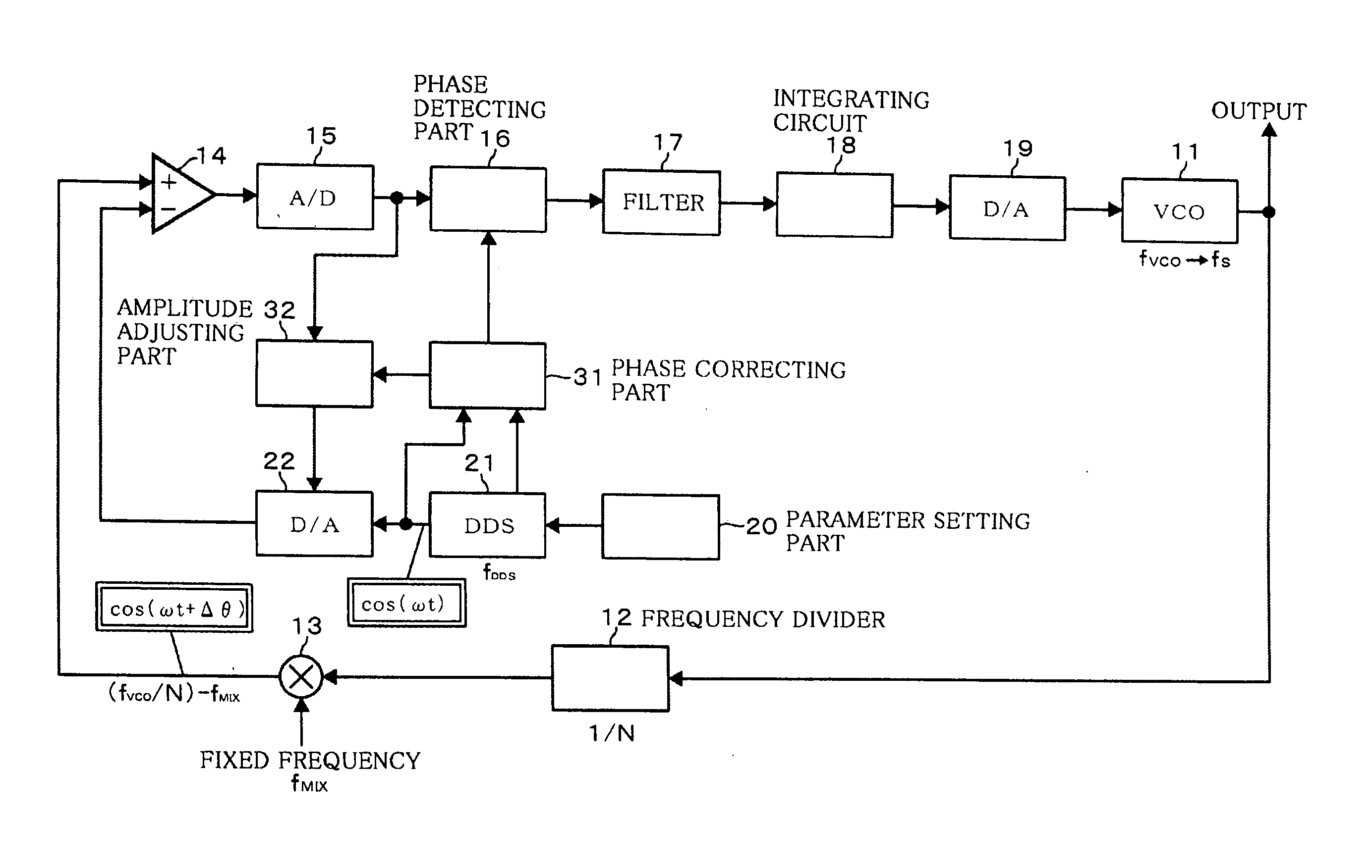
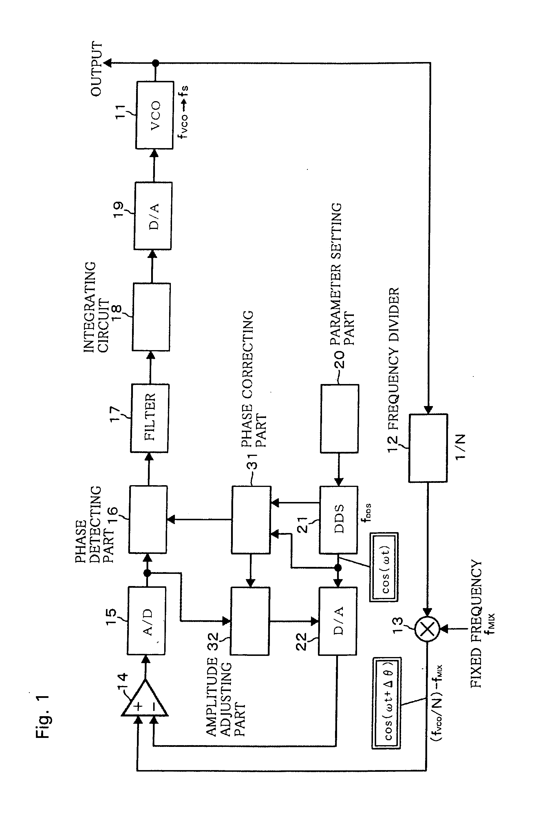
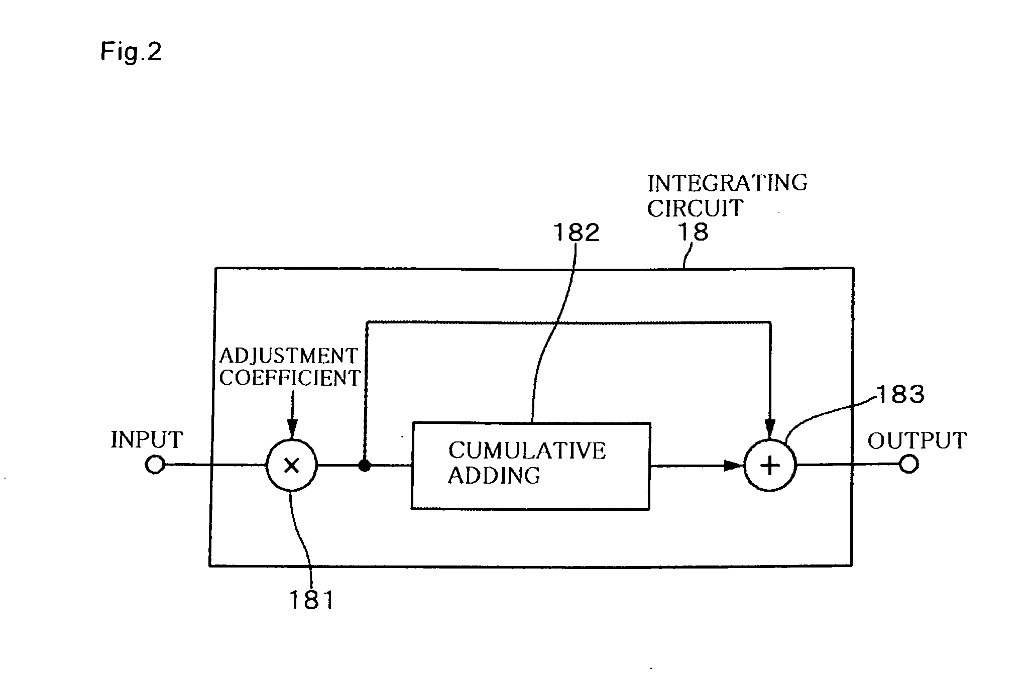
[0017]According to the present invention, the output sinusoidal signal corresponding to the output of the voltage controlled oscillating part and the set sinusoidal signal corresponding to the set frequency output from the frequency setting part are input to the differential amplifier after the control is performed so as to make the amplitudes of the both sinusoidal signals equal to each other, the output of the differential amplifier is converted to a digital signal in the A / D converter, the phase difference between the both sinusoidal signals is extracted by the quadrature detection of the obtained digital signal, the phase difference is integrated, and the resultant is input to the voltage controlled oscillating part. Since the amplitudes of the both sinusoidal signals input to the differential amplifier are thus made equal to each other, it is possible to increase a gain of the differential amplifier. Therefore, by making the gain of the differential amplifier larger than a maximum value of phase noise degradation of the A / D converter on a subsequent stage, phase noise level of the A / D converter is cancelled by an increase in power level by the differential amplifier, and as a result, the phase noise of the frequency synthesizer is improved.
Problems solved by technology
Method used
View moreImage
Smart ImageViewing Examples

Examples
example 1
[0058]The difference value between the sinusoidal signals was amplified by 26 bB (20 times) in the differential amplifier 14.
example 2
[0065]The frequency synthesizer was operated under the same condition as that of (Example 1), and the phase noise level was measured.
B. Experiment Result
[0066]The result of (Example 2) is shown in FIG. 5. According to the result of (Example 2), the phase noise level observed in the actual frequency synthesizer well matched the simulation result of (Example 1). From this, the effect of improving the phase noise level (effect of reducing the phase noise degradation) by providing the differential amplifier 14 was also actually confirmed.
Login to View More PUM
 Abstract
There is provided a frequency synthesizer capable of improving phase noise. A sinusoidal signal with a frequency set by a frequency setting part is output as a digital signal from a set signal output part, and the digital signal is D / A-converted. A difference between a sinusoidal signal with a frequency corresponding to an output frequency of a voltage controlled oscillating part and a sinusoidal signal output from a D / A converting part is amplified by a differential amplifier, and an amplified signal is input via an A / D converting part to a means for extracting a phase difference between the aforesaid sinusoidal signals. A voltage corresponding to a signal being the result of integration of the phase difference is input as a control voltage to the voltage controlled oscillating part. Then, a gain of the differential amplifier is set larger than a maximum value of phase noise degradation of the A / D converting part, whereby the phase noise degradation of the A / D converting part is cancelled.
Description
BACKGROUND OF THE INVENTION[0001]1. Field of the Invention[0002]The present invention relates to a frequency synthesizer.[0003]2. Description of the Related Art[0004]As a frequency synthesizer, there has been known one that A / D-converts (analog / digital-converts) an output signal of a voltage controlled oscillator, processes an obtained digital signal, and inputs the processing result to the voltage controlled oscillator, thereby forming a PLL (Phase Locked Loop). For example, a patent document 1 describes a frequency synthesizer that A / D-converts (analog / digital-converts) an output signal of a voltage controlled oscillator, quadrature-detects a sinusoidal signal generated from the resultant digital signal, extracts a rotation vector rotating at a difference frequency between the sinusoidal signal and a sinusoidal signal used in the detection, integrates a difference velocity between this rotation vector and a rotation vector rotating in reverse to the rotation vector and rotating at...
Claims
Login to View More Application Information
Patent Timeline
 Patent Type & AuthorityApplications(United States)
IPC IPC(8): H03L7/06
CPCH03L7/085H03L7/185H03L7/093
InventorAKAIKE, KAZUOTSUKAMOTO, NOBUOKOBATA, TSUKASA
OwnerNIHON DEMPA KOGYO CO LTD