Sound source separation and display method, and system thereof

Inactive Publication Date: 2011-03-31
NITTOBO ACOUSTIC ENG CO LTD
View PDF4 Cites 27 Cited by
  • Summary
  • Abstract
  • Description
  • Claims
  • Application Information

AI Technical Summary

Benefits of technology

[0023]According to the present invention, there is no need for a microphone for acquiring a reference signal. Even if the target noise phenomenon is so weak as to be hidden by other noise, it is therefore easily possible to perform measurement and evaluation, and noise-reducing measures can be taken effectively and easily. According to the present invention, it is also po

Problems solved by technology

In actual noise phenomena, it is often difficult to identify where the sound sources are.
For example, when noise with a predominant pure sound co

Method used


Image

  • Sound source separation and display method, and system thereof
  • Sound source separation and display method, and system thereof
  • Sound source separation and display method, and system thereof

Examples


first embodiment

[System Configuration]

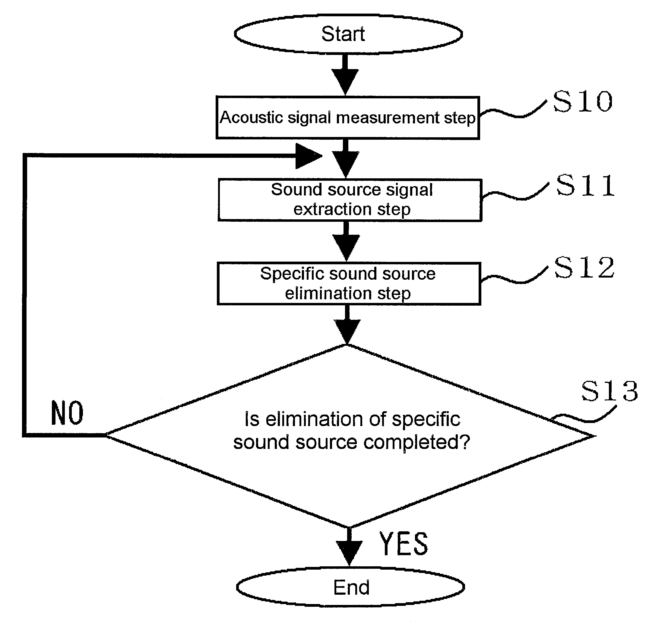
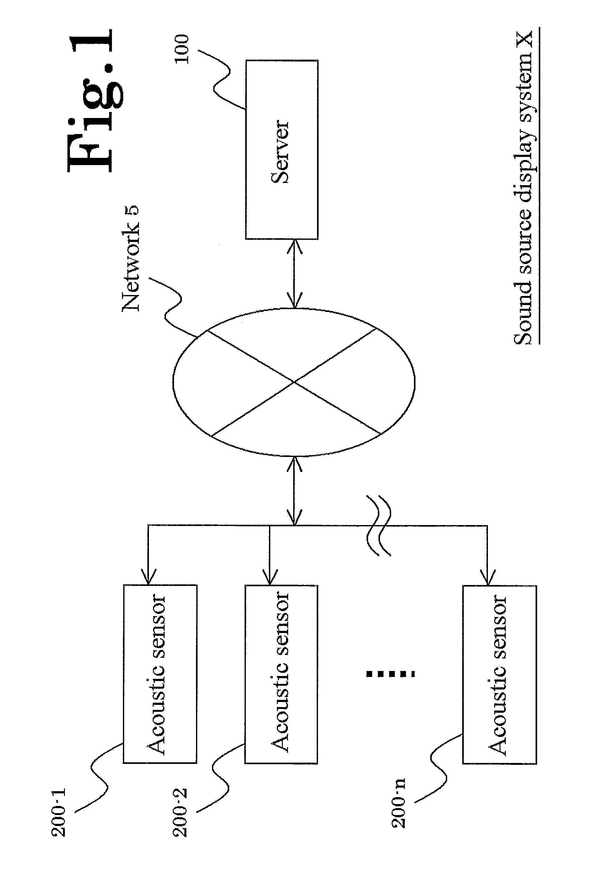
[0074]Referring to FIG. 1, the configuration of a sound source display system X according to an embodiment of the present invention will be described.

[0075]In the sound source display system X according to the embodiment of the present invention, acoustic sensors 200-1 to 200-n are connected to a server 100 (specific sound source elimination apparatus) which actually executes the sound source display, through a network 5 such as the Internet and an intranet. The acoustic sensors 200-1 to 200-n maybe arbitrary acoustic sensor devices for measuring sound pressure or particle speed, such as a microphone array for measuring sound pressure signals and acoustic particle speed sensors for measuring particle speed signals. The position of each acoustic sensor has arbitrary three-dimensional coordinates (x, y, z) so as to identify which acoustic sensor 200-1 to 200-n an acquired sound derives from. The acoustic sensors 200-1 to 200-n are preferably made of a sound sourc...

second embodiment

[0120]Next, a server 101 of a sound source display system according to a second embodiment of the present invention will be described with reference to FIG. 10.

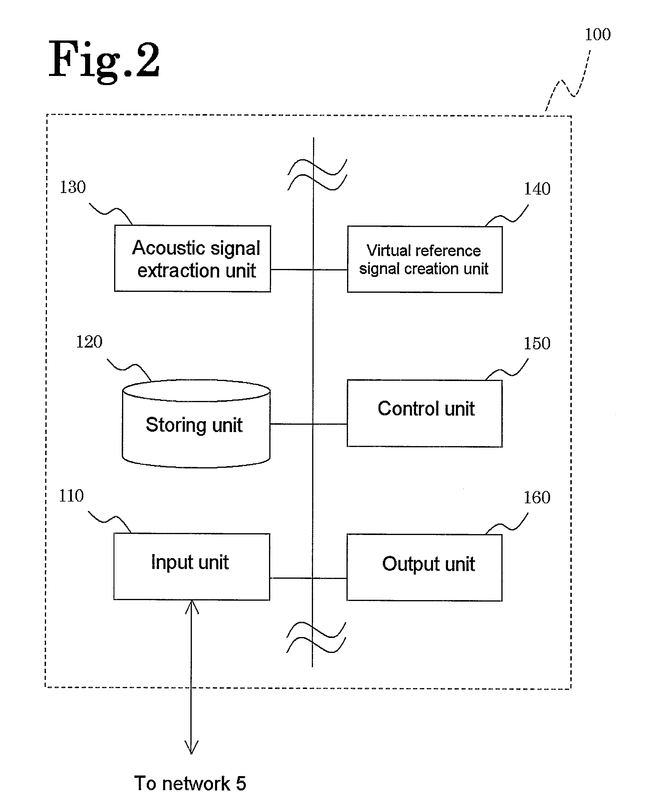
[0121]The sound source display system using the server 101 has the same configuration as that of the sound source display system X according to the first embodiment shown in FIG. 1. A difference lies only in the control configuration of the server 101. The server 101 differs from the server 100 in that there is added an acoustic signal cross spectrum matrix calculation unit 170 (acoustic signal cross spectrum matrix calculating means). The other components with like reference signs are identical to those of the server 100.

[0122]The acoustic signal cross spectrum matrix calculation unit 170 is an arithmetic unit such as DSP and CPU for calculating the cross spectrum matrix of acoustic signals. Like the acoustic signal extraction unit 130 and the virtual reference signal creation unit 140 described above, the acoustic signal cr...

example 1

[0149]With white noise of +20 dB as the masker on the left and white noise as the maskee on the right, the elimination of the masker was attempted by using the present invention.

[0150]In FIGS. 17 to 20, the open angle between the sound sources was changed to check if the masker could be properly eliminated, where the masker was white noise (+20 dB) and the maskee was white noise.

[0151]FIG. 17 is a diagram showing an example of the analysis result where the open angle between the sound sources was 30°, and the masker was white noise (+20 dB) and the maskee was white noise, both of which were a 1 / 1 octave band with a center frequency of 1 kHz.

[0152]FIG. 18 is a diagram showing an example of the analysis result where the open angle between the sound sources was 60°, and the masker was white noise (+20 dB) and the maskee was white noise, both of which were a 1 / 1 octave band with a center frequency of 1 kHz.

[0153]FIG. 19 is a diagram showing an example of the analysis result where the op...


PUM


Abstract

The present invention relates to a sound source separation and display method and a system thereof, and provides in particular a sound source separation and display method and a system thereof that are intended to eliminate a specific sound source. In order to separate a plurality of sound sources by using a single set of microphone array, the result of processing of sound source identification is utilized. More specifically, a signal in a direction is extracted from the result of the processing of the sound source identification, and a field limited to/eliminated of the effect of the signal is calculated and displayed. Such an operation can be repeated. A virtual reference signal can be created in a time domain.

Description

TECHNICAL FIELD [0001]The present invention relates to a sound source display method and a system thereof, and more particularly to a sound source separation and display method and a system thereof which are intended to eliminate a specific sound source.BACKGROUND ART[0002]A measurement system using a microphone array, which is a combination of a plurality of microphones, is widely used to identify and visualize the incoming directions of sound and the sound sources. The measurement system can be configured with only a single microphone array, or can also use several reference signal sensors such as a microphone and a vibration pickup.[0003]A microphone array by itself is used to equally evaluate sound sources lying in the intended direction of the microphone array. For example, a microphone array of planar shape is intended to analyze sound sources in the front direction. A spherical microphone array is intended to analyze sound sources in all directions around the sphere. If targe...

Claims


Application Information

Patent Timeline
IPC IPC(8): H04B15/00G10L21/0272G10L21/028G10L21/0308
CPCG01S3/8006G01H3/00
Inventor NAKAGAWA, HIROSHITAKASHIMA, KAZUHIROHIROSAWA, KUNIKAZU
Owner NITTOBO ACOUSTIC ENG CO LTD
Why Eureka
Try Eureka