Lens shift measuring apparatus, lens shift measuring method, and optical module manufacturing method

a technology of shift measurement and optical module, which is applied in the direction of optical axis determination, instruments, optical elements, etc., can solve the problems of inability to accurately estimate the position shift of the focusing spot of the laser diode by the lens when the optical module is assembled, complicated apparatus configuration, and increased manufacturing costs, etc., to achieve short time and simple configuration

Inactive Publication Date: 2011-03-31
RENESAS ELECTRONICS CORP
View PDF0 Cites 21 Cited by
  • Summary
  • Abstract
  • Description
  • Claims
  • Application Information

AI Technical Summary

Benefits of technology

[0022]According to the invention, the position shift amount of the focusing spot of the lens due to the eccentricity of the lens with respect to the frame body and the position shift amount of the

Problems solved by technology

First, since the eccentric amount of the lens is measured by rotating the lens-attached member, the rotating mechanism that rotates the lens-attached member is needed, the apparatus configuration is complicated, and a manufacturing cost increases.
For this reason, the position shift of the focusing spot of the laser diode by the lens when the optical module is assembled cannot be accu

Method used


Image

  • Lens shift measuring apparatus, lens shift measuring method, and optical module manufacturing method
  • Lens shift measuring apparatus, lens shift measuring method, and optical module manufacturing method
  • Lens shift measuring apparatus, lens shift measuring method, and optical module manufacturing method

Examples


first embodiment

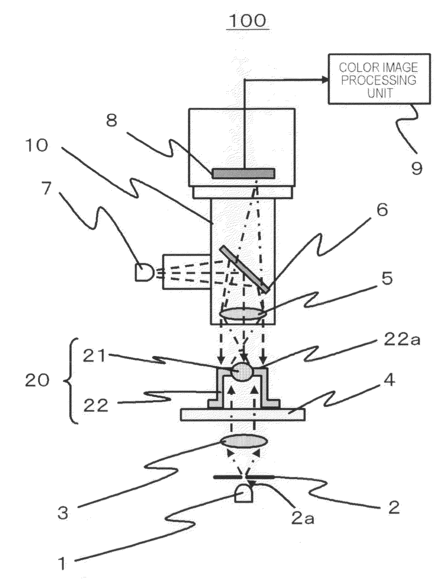
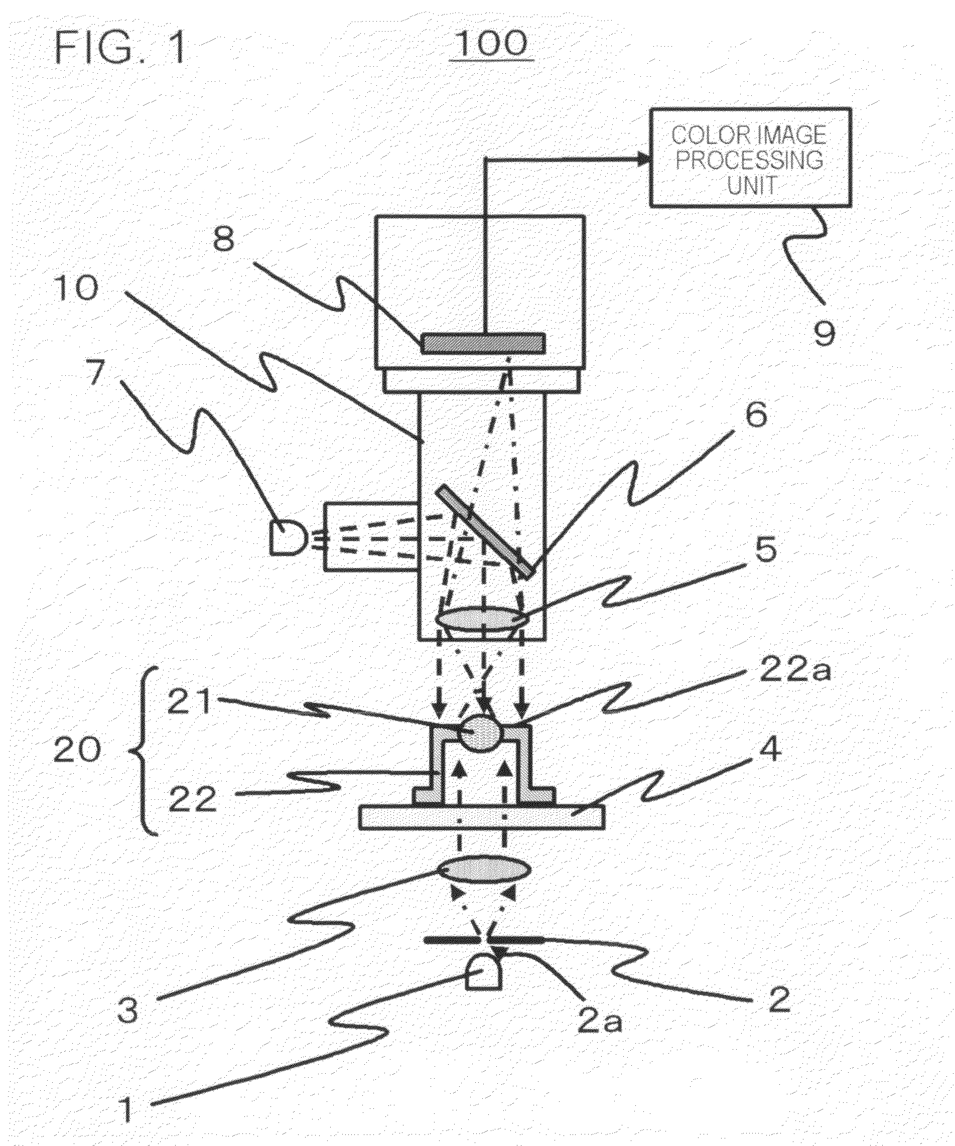
[0038]FIG. 1 is a schematic front cross-sectional view of a lens shift measuring apparatus 100 according to a first embodiment. FIG. 5 is a flowchart showing a flow of the operation of a lens shift measuring method according to the first embodiment. FIG. 9 is a schematic cross-sectional view showing an example of an optical module 150 that is manufactured by an optical module manufacturing method according to the first embodiment.

[0039]The lens shift measuring apparatus 100 according to the embodiment includes an irradiating unit (for example, configured using an epi-illumination light source7 to illuminate epi-illumination light and a transmissive illumination light source 1 to illuminate transmissive illumination light) that irradiates light onto a lens-attached member (for example, lens cap 20) that has a lens 21 and a frame body (for example, cap 22) to hold the lens 21, such that a reflected light from the frame body and a focusing spot 30 (see FIGS. 4A and 4B) formed by focusi...

second embodiment

[0130]FIG. 10 is a schematic front cross-sectional view of a lens shift measuring apparatus 200 according to a second embodiment. FIG. 11 is a flowchart showing a flow of the operation of a lens shift measuring method according to the second embodiment.

[0131]In the first embodiment, the example of the case where the wavelengths of the epi-illumination light and the transmissive illumination light are set to be different from each other, the image of the color of the epi-illumination light and the image of the color of the transmissive illumination light are extracted from the color image obtained by one-time imaging, and the image processing is executed respectively, has been described. Meanwhile, in the second embodiment, an example of the case where imaging based on the epi-illumination light and imaging based on the transmissive illumination light are performed at different timings will be described.

[0132]In the case of the embodiment, the wavelengths of the epi-illumination ligh...


PUM

PropertyMeasurementUnit
Wavelengthaaaaaaaaaa

Abstract

The lens shift measuring apparatus calculates a position of a predetermined portion of a frame body, on the basis of an imaging result obtained by imaging reflected light from the frame body, in a state in which light is irradiated onto a lens-attached member having a lens and the frame body to hold the lens, such that the reflected light from the frame body is generated, and calculates a position of a focusing spot, on the basis of an imaging result obtained by imaging light transmitted through the lens, in a state in which the light is irradiated onto the lens-attached member, such that the focusing spot formed by focusing the light transmitted through the lens by the lens is generated, and calculates a shift amount of the position of the focusing spot with respect to the predetermined portion as the shift of the lens.

Description

BACKGROUND[0001]This application is based on Japanese patent application No. 2009-224989, the content of which is incorporated hereinto by reference.TECHNICAL FIELD[0002]The present invention relates to a lens shift measuring apparatus, a lens shift measuring method, and an optical module manufacturing method.RELATED ART[0003]For example, in a CAN package of an optical semiconductor element that is used for optical communication, it is general to perform packaging using a cap (hereinafter, referred to as lens cap) where a lens is hermetic sealed to a central portion, in order to obtain optical coupling with an optical fiber or optical coupling with a receptacle to connect the optical fiber. The lens cap is hermetic sealed by resistance welding with respect to a disk-like block (stem) where a chip, such as a laser diode, is mounted.[0004]When the lens cap is hermetic sealed, the stem and the lens cap are positioned on the basis of the external positions thereof and are welded to each...

Claims


Application Information

Patent Timeline
IPC IPC(8): G06K9/00B32B37/02
CPCG01M11/0221G02B6/4204G02B6/4227G02B6/4222G02B6/4221
Inventor TANAKA, YOSHIHARU
Owner RENESAS ELECTRONICS CORP
Why Eureka
Try Eureka